New Regulator Comparison

How wonderful to have a trap that “just works.” Substituting a new regulator for the original Defender and Liberty regulators has resulted in a so-far perfectly stable system, without the “abnormal combustion” problems that had been plaguing the 2002 Mosquito Magnet Defender for over a year now, or longer.

140,000 BTU Regulator

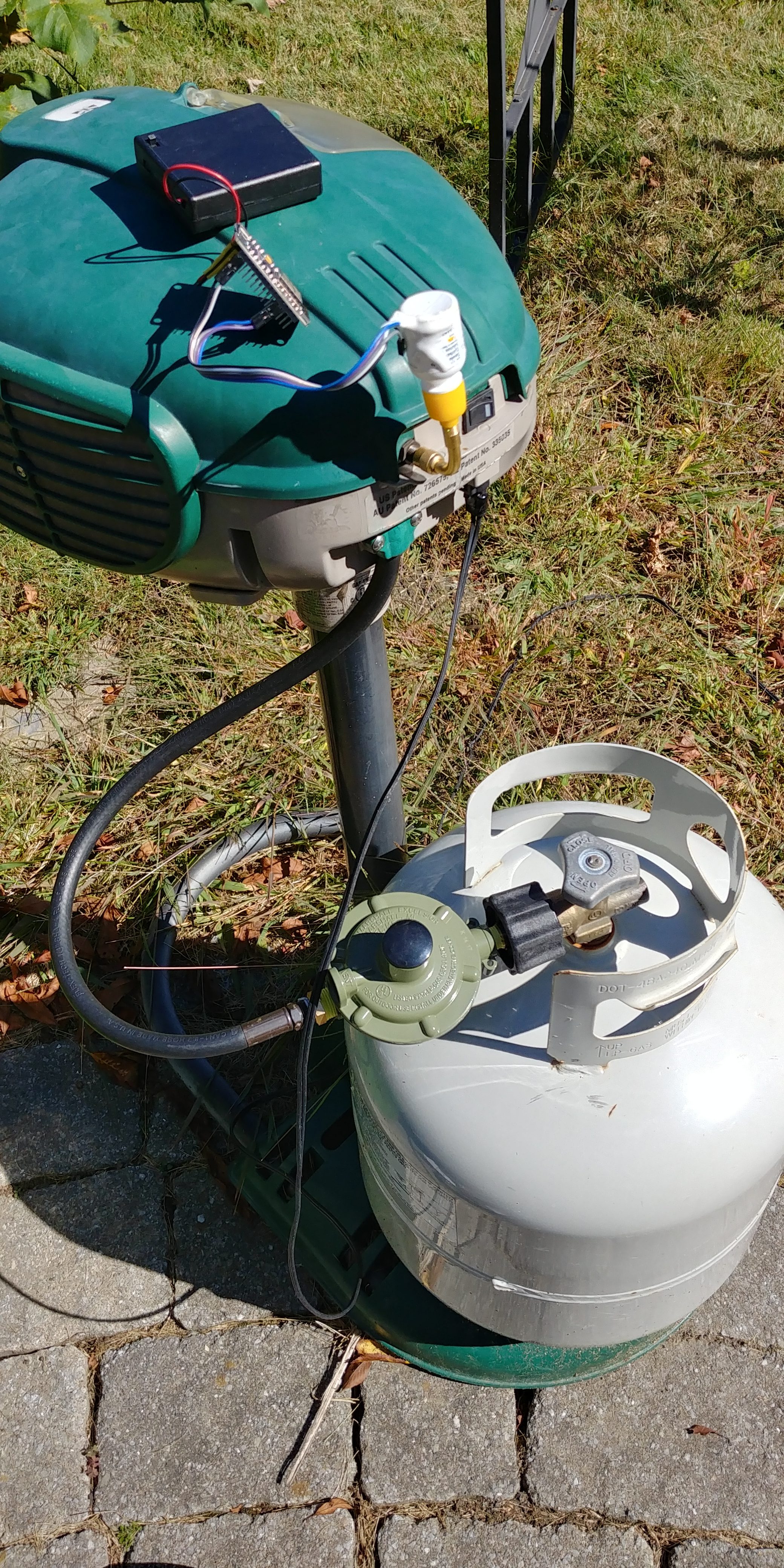
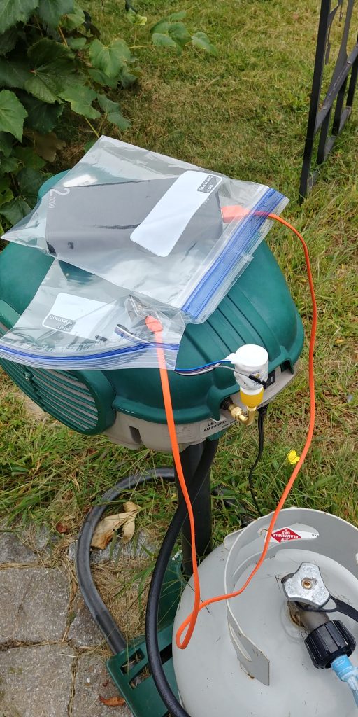
The first regulator was a high (140K) BTU with a no attached hose, similar to the original regulators. It is larger and more expensive than the standard replacement regulators, including the one used on the Mosquito Magnet Patriot. However, it had a removable cap that possibly supported adjusting the output pressure, and the existing hose could just screw in via an adapter to match the thread sizes. The parts are Marshall Excelsior MEGR-230 with an Acme Nut to 1/4″ M NPT to attach to the tank, and a 1/4″ F to 3/8″ M NPT fitting to match the existing hose. The total cost was about $27, higher than the standard replacement units. The cord comes out the back instead of the side, which sticks out and looks a bit awkward. This regulator provided almost exactly 11.0 inWC pressure.

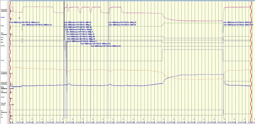
However, when the pressure probe was attached, the rush of propane into the small bottle did set the combustion to the abnormal, rough mode. The trap did not recover on its own within a minute.

Standard Regulator Hose with 3/8 Flared Nut and 1/4″ Adapter

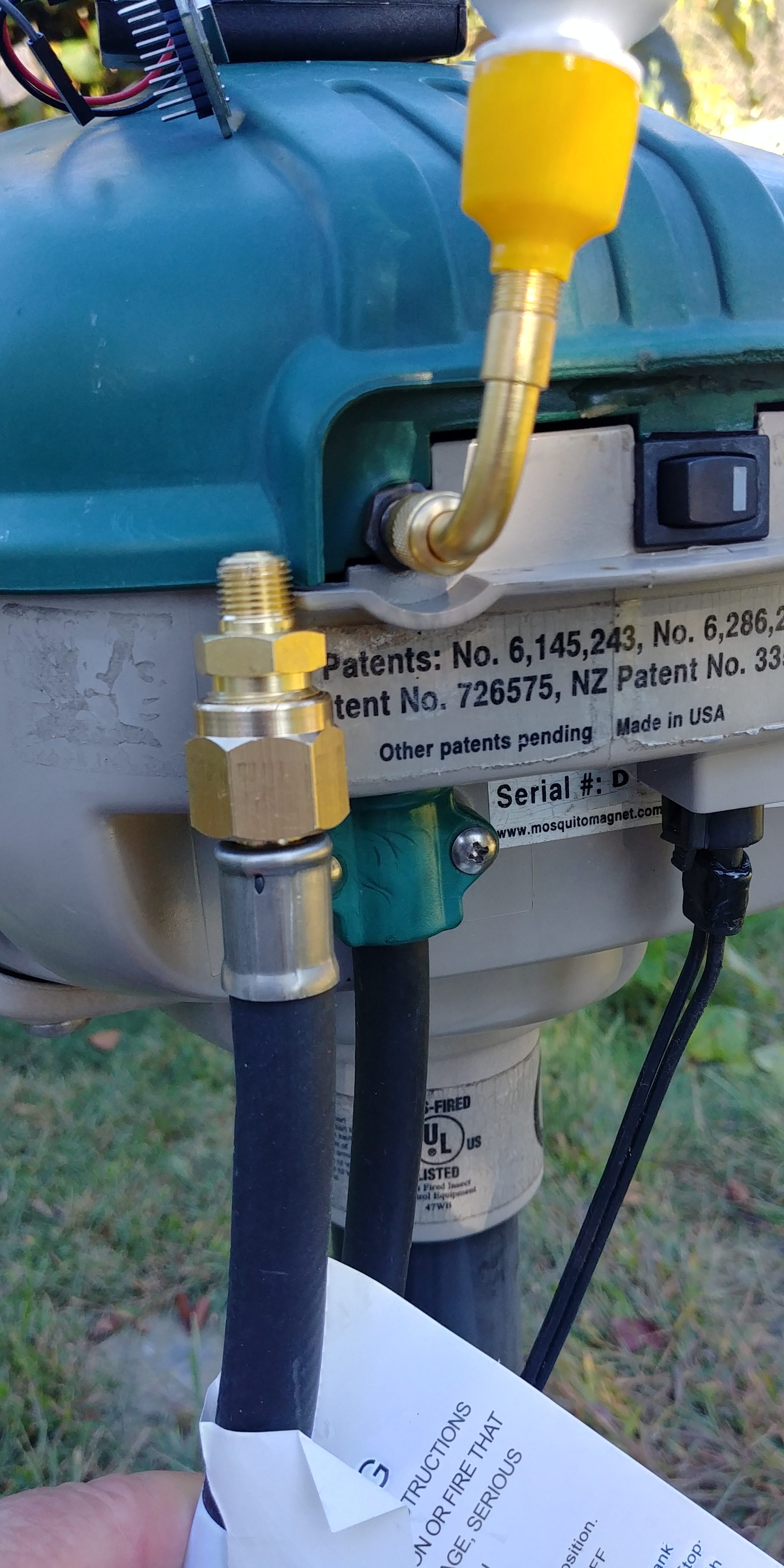
The standard regulators come with permanently attached hoses with a 3/8″ F flare connector. The hose is a bit larger than the original, but the connector is much larger, and requires another large adapter to screw into the Defender valve assembly. Thanks a lot, safety people. Holding the hose and adapter against the Defender, it looks like the fittings are too large to fit inside the case vertically, and the large nut may not fit through the case hole. This may be investigated during the off season, but using the standard hose doesn’t look promising, especially considering that the Mosquito Magnet Patriot uses an external adapter on a short cable to connect to the valve inside the trap.

The work-around is to use a 3/8″ M Flare to 1/4″ F NPT coupling ($4), and tie the two hoses together, like the Patriot, except that the original hose is now much too long for a neat installation. Perhaps the hose can wrap around the tank.

Another approach, used in the Patriot, is to shorten the hose from the Defender and attach a new 3/8″ male flare fitting. Alternately, remove the 3/8″ female flare fitting and attach a new 1/8″ male fitting. Acquire a hose kit with barb fittings, ferrules, and a vice-grip-looking crimper for about $50, and away you go (but no leaks allowed). This is too much for me.

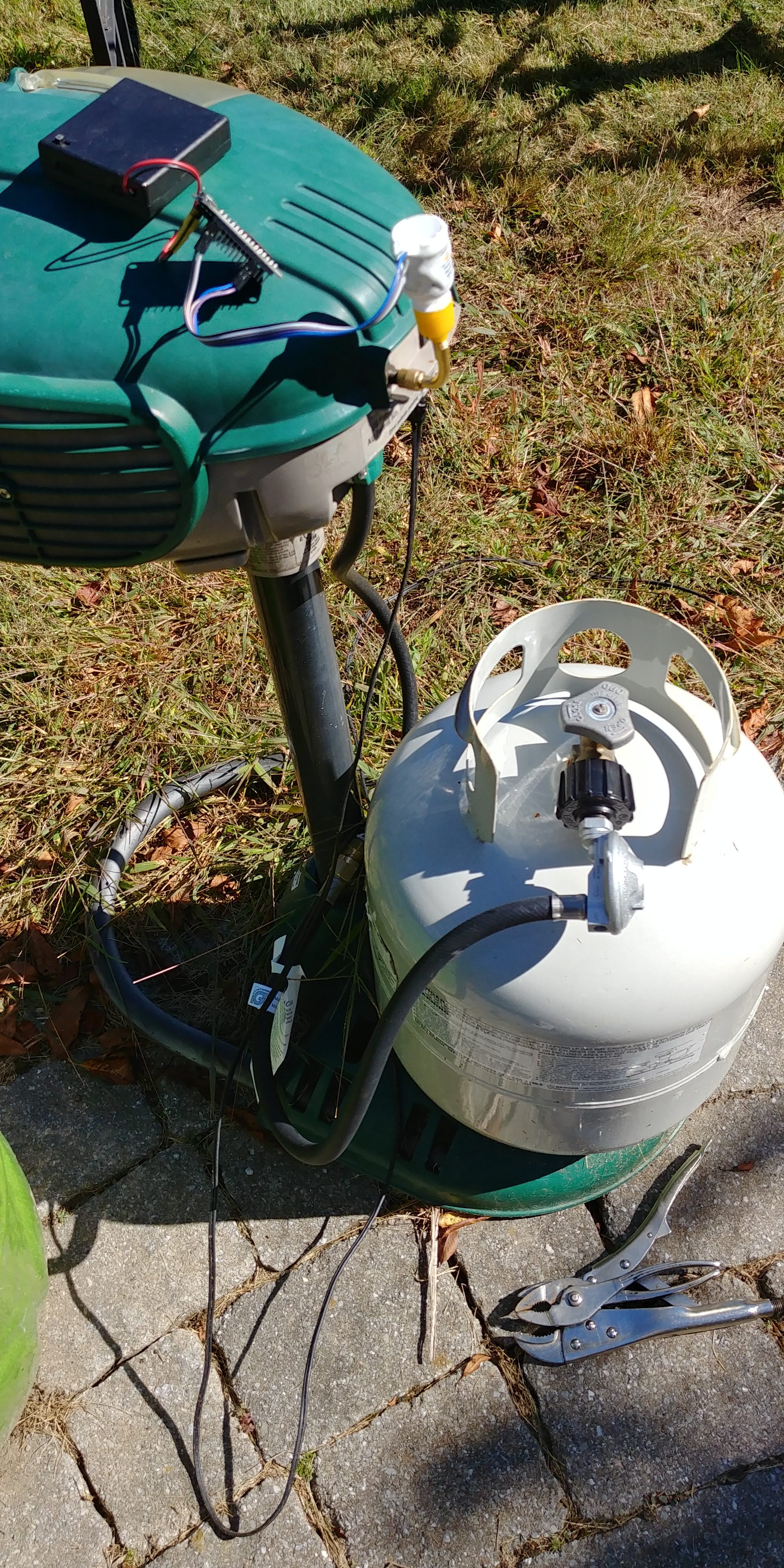
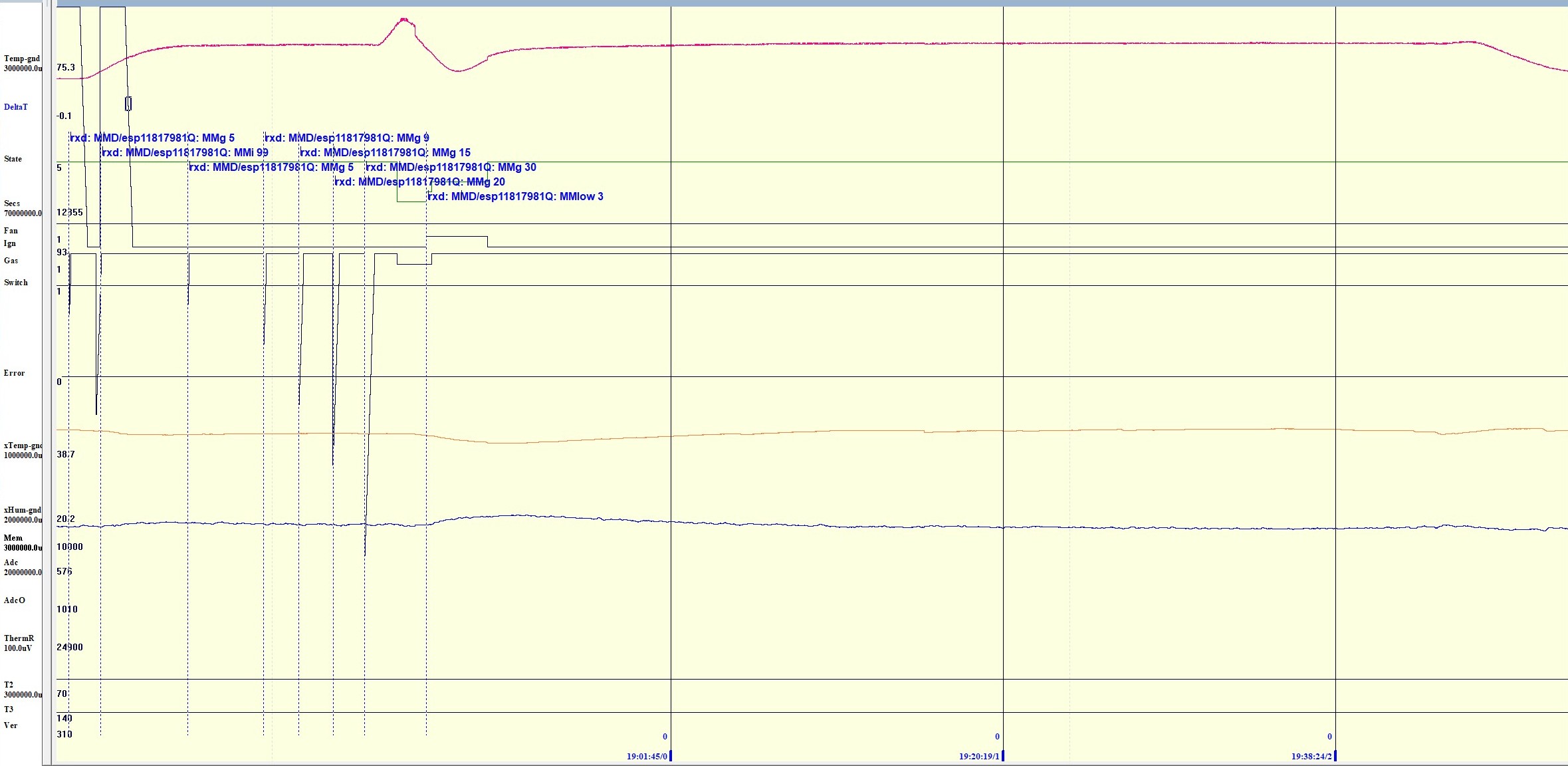
The IGT 2.8 KPa 2′ Hose Regulator ($10, total $14) used in the Patriot was installed. The unit is rough and dull, but is configured similarly to the original regulator. It put out ~10.5 inWC pressure, but provided a 95°C exhaust temperature rise for 80 minutes with no problems. It was taken out of service to test the third regulator.

Right-angle standard regulator

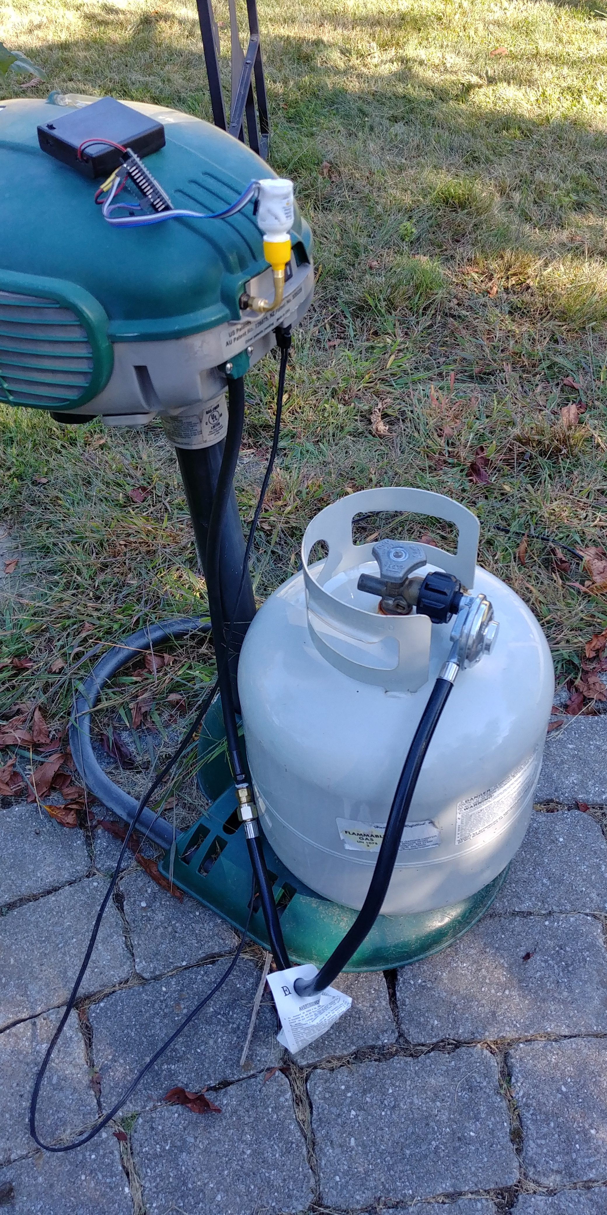
The last test used the Dozyant Vertical 2′ Hose Regulator ($10, total 14). This unit is shiny smooth. The hoses dangle and wrap as the other regulator. It puts out close to 11 inWC pressure. However, after a little less than an hour running, the temperature rise above ambient went from 95°C to 100°C, then the exhaust temperature dropped to 80°C, just like the old defective regulators. Upon restart, the unit reached a 100°C exhaust rise from ambient, then after a little more than an hour, went to 105°C above ambient only to drop to 80°C (55°C above ambient). This repeated failure disqualifies the Dozyant. The unit was replaced with the IGT unit for further testing.

All of these regulators provide a relative pressure output, that is, the output pressure of 11 inWC is relative to the atmospheric pressure. So if the atmospheric pressure is 30.13 inHg or 409.24 inWC, and the pressure at the Schrader valve is 30.89 inHg or 419.49, the regulator output is the difference, here 10.25 inWC, which is close (but not that close) to the rated 2.8 KPa (kilo-Pascal) or ~11.4 inWC specified for the IGT regulator.

After almost 3 hours, it was time to remove the exposed battery operated pressure sensor. The IGT trap was running at 115.9°C exhaust with ambient air intake 17.8°C and 70.1% relative humidity when the pressure sensor was removed from the Schrader valve. The temperature difference of 98°C was a bit high, but so was the humidity, which makes the air mixture less dense, and the expected temperature rise higher.

The absolute pressures were 419.69 inWC attached and 409.70 (30.17 inHg) removed for a difference of 10 inWC. This is more than 10% less than 11.4 inWC. The 30.17 inHg is what one might call “mean pressure” discussing weather: in the last month, the pressure ranged from a low of 29.71 to a high of 30.59. It would be better if the output pressure were closer to spec or at least 11 inWC, but perhaps the 5%-10% difference will not be significant, as long as the pressure is constant and not irregular. On the plus side, it may conserve propane.

However, like the more expensive unit first tested, removing the pressure gauge caused the trap to enter the dreaded “abnormal combustion” phase. The exhaust temperature difference rose to 121.7C (105°C difference), then fell to below 70°C, and the trap entered the fault state. All of this was caused by a momentary dip in pressure from quickly removing a gauge from a Schrader valve. We cannot expect any regulator at the end of a hose to compensate for a sudden pressure change next to the flame, so the removal does not reflect badly on the regulators, but does demonstrate the importance of maintaining a steady, constant pressure.

Sudden pressure fluctuation is now the prime suspect in triggering the abnormal combustion. This characteristic is not very important for barbecue grill regulators, which average the flame over a relatively long time. We shall see how this unit performs on the Defender, which requires a very steady flow to maintain its small flame. A test failure does not mean that the unit is defective for its intended use, it just means it didn’t work well in the Defender. We are depending on an unspecified behavior of a mass market commodity consumer device, not the safest strategy.

The pressure sensor is capable of over 100 samples per second pressure acquisition from the chip and an unknown but sufficient rate from the software, but transmitting the data is another challenge. Properly designed, the system is likely fast enough to detect problematic pressure fluctuations, however, getting the pressure sensor working and recording high speed looks like a winter project. We would also need an quick response “abnormal combustion” detector. Audio or vibration sensing might work. Perhaps, by some stroke of luck, none of this will be necessary.

To achieve relative regulation, the regulator needs a port (hole) to measure the atmospheric pressure. These ports are subject to contamination. The regulators themselves typically have instructions to install under protective cover. Of course, no one does that, but from now on, it may be a good idea to follow the directions. We are really looking for that “just works” magic, and a “protective cover,” like an iPhone case, adversely impacts the industrial design of the system.

So at this moment, the Dozyant unit failed the Mosquito Magnet Defender test, and the IGT unit is now under test. Stay tuned for test results. If the IGT unit fails soon, this paragraph will be updated with the results. One update has already been made. Otherwise, a new entry will be posted.

New Regulator Eliminates Abnormal Combustion

After some experimentation with two original regulators, one from a Defender and the other from an older Liberty, it seemed like it made no difference in the abnormal combustion phenomena from which my Mosquito Magnet Defender has been suffering. A new high quality regulator that might support some range of pressure adjustment and an adapter for the existing hose was put in service.

The pressure NodeMCU described earlier measures the absolute ambient pressure with the gas valve shut. Opening the valve yields a higher reading, and the difference is the gas relative pressure.

The new regulator output was nearly exactly 11.0 inWC, a bit higher than the old Defender’s 10.5 and the older Liberty’s 9.5. It looked like there was no need for adjustment. Remarkably, the trap reached its operating temperature and stayed there without rapid increase or decline. Over night, the combustion temperature declined, but then rose the next day. The system seems stable.

I then realized something after re-reading the forum post from another contributor, who posted graphs showing combustion chamber exterior temperature vs ambient as offset by a more or less fixed amount. Perhaps there is no such thing as a fixed “operating temperature.”

The thermistor doesn’t actually measure combustion temperature, but rather exhaust temperature after the catalytic converter. At this point, all the unburned propane and CO and should have been combusted then converted to CO2, and the air stream should be fairly laminar. This implies that the temperature being probed by the rod is measuring how much heat energy is being added to the input air stream by the propane, and not the flame temperature. Using this principle, we would expect a more or less fixed temperature rise over the ambient air temperature, because a BTU’s worth of energy from propane adds that energy to a certain amount of air, and results in a certain amount of temperature rise. So, in a properly working trap, the measured exhaust temperature should equal the ambient temperature plus a more or less fixed amount depending on the air and propane flow, assuming complete combustion. If the temperature drops 20°C, then the exhaust temperature should go down the same amount, and there should be no worry when the exhaust temperature drops to 90°C or below.

The exhaust temperature rise seems to be about 100°C measured at the thermistor, which is connected to the exhaust through a metal rod with some unknown thermal impedance, but I doubt it is dropping 50°C along the rod. I would feel better about this explanation if my calculations of temperature rise were within an order of magnitude of measured, but no, they are not. Starting with propane flow BTUs per second, and In^3/Sec exhaust flow, it should be possible to calculate the temperature rise, but this analysis is not working today.

Nonetheless, this is an exciting development. Besides that, the most important thing is that the trap is stable for now. Perhaps the time has come to move the temperature/humidity sensor to the air & mosquito intake stream. Then the temperature differential can be accurately measured and this theory supported with experimental evidence.

Regrettably, the original Defender regulators are no longer available. The modern inexpensive regulators come with a fixed cable attached, and the fitting does not match the Defender valve, but requires an adapter that may not fit completely in the case. Of course, the heavy duty regulator with fittings works with the existing cable, but it is overall twice as expensive, a bit larger and awkward. It may not perform well long term because it is designed for a much higher flow rate. We shall see.

P.S. The Patriot uses an inexpensive ($10) IGT A300USL L.P. Gas 2.8 KPa (11.4 inWC) regulator. This, as all other modern replacement regulators, requires a fitting to match the 1/8″ NPT female on the valve inside the Defender.

The temperature/humidity sensor has been moved to the vacuum intake side of the trap to measure the incoming air. At 25°C 50% RH intake, the temperature differential is about 95°C. I expect the humidity to play some role here. I will measure and publish more data when it becomes available as the trap runs during various weather conditions.

Regulator Ok?

Investigating the abnormal combustion temperature, I wanted to eliminate the issue of a faulty regulator, which was the original from 2004. I also wanted to double check the gas valve mechanism to make sure that it was actually allowing the flow of gas. I purchased new regulator and tank fitting parts. It was important to get a regulator that could be adjusted somewhat to match the original. Almost all low pressure regulators are set to 11 inWC (inches of water column), and it looks like they cannot be adjusted. The high pressure regulators go from 0-40 psi, which would not be expected to do well in the 1/3 psi range used by low pressure appliances.

But first, I needed a way to measure the existing regulators, so that I might match the output propane pressure, necessary for correct operation as originally designed. I didn’t want to build a water column manometer, plus I wanted something wireless, so I could analyze the pressure as the temperature fluctuated. See the previous post.

It’s hard to see, but there is a right-angle Schrader extension (yellow) connecting to the quick clear Schrader value. The extension releases the trap valve to allow gas to flow. The other end, with the Schrader core removed, is screwed into an empty plastic eye drop bottle, machined to just fit over the valve thread for a tight fit when screwed together. A slot sawed through half of it’s side on the bottom allowed opening a flap enough to insert a BMP180 barometric breakout board, connectors, and wires. The flap and the connecting wires are sealed to the container with two rounds of casting plastic applied freehand. As usual, it is a bit sloppy and not the best job, but it seems quite solid. The wires plug into a backup NodeMCU running the trap software with the BMP180 temperature/pressure sensor driver substituted for the HTU21D temperature/humidity driver. The orange cable connects the NodeMCU to a high-capacity charger brick for power. It should run for quite a while, and is easier and safer than running more AC power to the trap. I am fairly confident that the bottle does not leak appreciably. Of course, I should have attached it to a bicycle tire to measure the pressure long term, but I was in a hurry for results.

And results I got.

Temp=67C (-0.4) at 3:0 F=1 I=1 G=0 S=1 E=0 T=35.8C H=24.2% M=11232 (651/1013:33851) R=70~140 B=1.0 V=3.1
Temp=-43.7C (0) at 0:109 F=0 I=0 G=0 S=0 E=0 T=20.6C H=30.48 inHg, 413.87 inWC% M=20872 (9/9:18804706) R=40~140 B=0.0 V=3.2
Temp=67.1C (0.1) at 3:1 F=1 I=1 G=1 S=1 E=0 T=35.8C H=24.3% M=11232 (648/1010:33695) R=70~140 B=1.0 V=3.1
Temp=-43.7C (0) at 0:110 F=0 I=0 G=0 S=0 E=0 T=20.6C H=31.19 inHg, 423.53 inWC% M=20872 (17/16:18804706) R=40~140 B=0.0 V=3.2

Two data streams are interleaved as the trap just turned on the Gas. With the propane off (G=0), the pressure is 413.87 inWC. With it on (G=1), the pressure rises to 423.53. The pressure from the regulator is the difference, about 9.5 inWC, which is close to what is expected from a gas grill regulator. This particular regulator is from my old Liberty. I will later replace it with the decrepit original Defender regulator and measure it.

In this run, the temperature went up to 115°C, then dropped again down to the 70°C range. During the run-up, the pressure was 423.30 inWC, and at the peak (when the combustion changed to abnormal) it was 423.41 inWC, not much difference.

So I didn’t see any fluctuation in the pressure that would trigger a temperature drop, but I did notice something else. When operating normally, the trap noise almost all comes from the fan. But there are times when there is a very pronounced, rough burning sound from inside, a like a blow torch or jet engine. A couple of times, it matched the combustion mode change. Normal, quiet. Abnormal, noticeable rough sound. I conclude that this rough sound is an uneven, chaotic burning and is a related to the abnormal temperature issue.

So what could cause this to occur occasionally (although right now, almost every time)? Perhaps the pressure is just wrong, stable as it seems when measured every second. Perhaps a higher frequency pressure disturbance not caught by the gauge reporting at 1 sample/second is the problem (the BMP180 runs at about 128 samples per second). Perhaps the atmospheric pressure is changing and the regulator is not keeping up quickly enough. Perhaps the nozzle is somehow clogging and shooting off a long, uneven stream. Perhaps the air intake via the fan is too strong and the mixture too lean, or the gas flow and flame is too large for the chamber. The system seems so fussy. Also unexplained is yesterday’s gas interruption for 30 seconds setting off a very quick temperature rise, abnormal the other direction, although a small, brief temperature rise and peak is observed before the fall in nearly all cases.

The igniter on for 120 seconds command resulted in a temporary temperature rose from 78.6°C to 80.7 °C that fell back after the igniter went off. This, plus previous attempts, indicates we cannot recover using the igniter by itself.

Turning the gas off for 25 seconds, then 10 seconds later (to allow 15 second warm up), turning the igniter on for 50 seconds, restarted normal combustion.

This sequence could be added to the controller program, but I am concerned by the wear on the igniter if this keeps cycling several times per hour or day. I would rather look for other methods to control this issue. Perhaps the new nozzles are somehow misbehaving. Perhaps the fan might be used to bring the combustion under control. With the additional memory available with the new NodeMCU LFS firmware, it might be time to implement full range pulse width modulation (PWM) for the fan control, rather than the simple 10 ms duty cycle startup algorithm in the main loop (matching the original controller).

Substituting a full propane tank for the 85% empty (3# remaining) tank resulted in a pressure of about 11 inWC, exactly what the fixed regulators typically provide. On restart, the trap climbed to 120°C and has stayed there for a while, unlike with the other tank. It is hard to believe such a small pressure difference between 9.5 and 11 inWC would make such a difference, but I suppose anything is possible. According to Arthur Conan Doyle, “Once you eliminate the impossible, whatever remains, no matter how improbable, must be the truth.”

Oh, by the way, today with the trap running mostly at 70°C and an old attractant, there were still 3-5 live mosquitos at noon in the catch basket. So maybe none of this abnormal combustion stuff really matters.

This is a work in progress. Stay tuned

Mysterious Combustion & Additional Software

Mysterious Combustion

My Mosquito Magnet Defender has been unreliable in so many ways, most of which I have fixed. However, a remaining issue has me stumped. After a period of normal operation which could last an hour or days, the combustion temperature inexplicably rises a bit, then falls to around 70-80°C. Prior observations found that the trap does not catch any mosquitos running at those low temperatures, but does catch thousands at its normal temperature of 110-120°C.

Yesterday, after the trap failed, I experimented a bit with the Add-On controller commands to see if I could recover, and if I could trigger this misbehavior.

Defender Abnormal Combustion Cycles, Recovery, and Tests. The vertical lines are 1000 samples or about 17.6 minutes apart.

The Mosquito Magnet Defender IOT Add-On reports about 19 different measurements or parameters once per second. See Status Report. The most important of them are displayed in the above graph (click to see larger), which displays almost a full day’s operation. The most important value is the combustion temperature measured by the thermistor (top trace), which is glued to a thermally-insulated rod of metal that is inserted into the combustion exhaust after the catalytic converter. This rod takes several seconds to conduct heat from inside to the thermistor. Both the original controller and the Add-On make all their decisions based on the measured temperature and elapsed time.

The graph shows a combustion start up with the temperature rising to 120°C, peaking at 123°C, then dropping to 80°C. It worked normally for only about 10 minutes. After checking the trap, I restarted it at 14:47 and it ran until 17:26 when it did the same thing. Thoroughly irritated, I ran a series of tests to see how the trap could be recovered, and what might trigger the problem (see below). At 22:26, I used gas off and ignition on commands to successfully restart combustion, which ran normally until 23:33 when it peaked and dropped again. It ran in this state until the temperature cooled below 70°C, which was the programmed low temperature limit. The trap then entered a fault condition, where it stayed until 9:04 the next morning, when I used the web page to reboot it. I set the under and over temperature limits to 40°C and 161°C in preparation for even more testing later.

Abnormal Combustion Testing: Recovery and Triggering. Here the vertical lines are about 18.5 minutes (more missing samples).

(Click to see larger.) During the testing, I turned on the igniter for 99 seconds, then turned off the gas for 5 seconds to exercise the valve, perhaps flex the regulator, or disturb some weird combustion mode. That was successful in restarting the trap, which reached 115°C. I then experimented with stopping the gas for 5, 9, 15, 20, and lastly 30 seconds. While the gas was off, the temperature held steady, which is to be expected because of the thermal inertia of the temperature probe bar. After the gas came back on, the temperature still held steady, which implies that something is hot enough to reignite the propane, or that combustion never stopped. However, after the 30 second interruption, the temperature started to rise after about 25 seconds, climbing to 140°C and beyond, at which point the controller detected an over temperature condition, and restarted the cycle, which turns off the gas and cools the chamber to the start temperature. I don’t know how high the temperature might have gone without that intervention by the software. At 18:48 I gave an MMlow command to restart the ignition, and the trap recovered going down to 84°C then back up to 112°C, where it stayed until 19:45, where it peaked and dropped again.

Perhaps the trap should let the temperature rise even higher at which point the combustion weirdness mode might correct itself. However, the NodeMCU has a certain rated temperature range, and I don’t want to get too close to the high temperature limit. However, these recent field failures showed only a very modest 2-3°C temperature increase before dropping, so the over temperature limit was not a factor here.

The 30 second gas shutoff experiment yielded unexpected results that mirror the phenomena seen in the past. How could shutting off the gas flow, then restoring it, cause this to happen? Perhaps there is some funny combustion mode that causes the propane to burn inside the catalyst cylinder instead of the front chamber, putting the hot part of the flame on the thermistor probe. Or maybe the flame is just burning hotter somehow. But how and why?

How can I figure this out? What sort of instrumentation do I need? I cannot just open the chamber and look in. Before installing another 5 or so temperature probes, defacing the trap, I should to eliminate other possible causes. The most obvious cause might be a problem with the gas feed from the ancient regulator. Of course, replacing the regulator would be the obvious step here, but the catch is that the original Mosquito Magnet regulator is an adjustable low pressure regulator, and I do not have the specs for it. The low pressure regulators I can find today are fixed pressure at 11 water column inches. This may be Ok, or maybe not. So now I need a way to measure low gas pressures 1) to see what the original regulator does, and 2) to measure the pressure during operation. My sports gauge is fine for basketballs and footballs, but not sensitive enough to measure 11 wci (1 psi = ~27 wci).

So I ordered some parts, in particular a barometric gauge which will measure absolute pressure. I haven’t bothered to check whether it will be sensitive enough, or too sensitive, because I am working from the hobbyist perspective of “what I can get” rather than “what I must have.” I can hardly wait to mount this device in some sort of sealed bag or balloon, attach it to the trap’s Schrader valve (dangerous!), run wires into the controller, and add additional software to measure and report the pressure. Wish me luck, or at least, a speedy recovery!

Additional Software

So now we want to add a pressure sensor? And what about the helpful propane tank weighing device? And the alive mosquito detector? And the Real time clock? And real pulse width modulation for the fan, perhaps to control combustion temperature? All of these functions take RAM memory, which is very limited on the Add-On’s NodeMCU Lua environment.

The good news is that, as a result of the Add-On Construction Details project, I have finally tried using the new so-called “LFS” system for running Lua code from the flash memory instead of RAM, and the results have been amazingly good. The current software running on the new system has ~35kb of free RAM where it has only ~11kb on the old. These are very small numbers, but the NodeMCU is a very small system. It feels like such a victory, it overshadows the problems in my Defender, at least for the moment. The new system is so much better, it makes up for the trouble it took to set up my own Lua environment build system, although that was not really necessary, as I could have used on-line tools to accomplish the same result. But now, I have the conceit that I am a master of my own destiny, which is good to have now and again.

All this means, the construction details wiki page needs more updating, and the progress percentage should be reduced, but of course that never really happens, and is part of the reason why the last 10% of a project takes nearly forever.

New Wiki Page & Incomplete Combustion

For the last week, I have been trying to write a wiki article Mosquito Magnet Defender IOT Add-On Construction Details, which is now at 93 percent. The article was inspired by another DIY enthusiast who published his invention on the forum. This effort has been a major time sink, as I go deeper and deeper into programming and testing. This is not the same as catching mosquitos, or fixing my poor old Mosquito Magnet Defender, which suffers from so many ailments.

It is so difficult to write what is true. It is much easier to write what I think is true. The article contains directions for building an add-on to the Mosquito Magnet to support diagnostics and remote control. But do the directions work? Are they sufficient? I just followed the directions to install some firmware, and was disappointed to find that what I did last year no longer works this year. So now, new old directions, plus posting last year’s firmware to download on this site.

It is frequently said that the last few percent of a project is the hardest, and it looks like this project will be no exception.

While I was away on vacation, the trap ran out of gas. I forgot to load a full tank before I left, and didn’t think to ask the house sitter to check the tank. Instead, I was frustrated when checking the trap from afar, which was an unintended consequence, not to mention missing over 2 weeks of mosquitos.

I needed a means to report the propane level. This could be done by adding a weight sensor to the tank, or a pressure sensor to the propane line, which would display in the status report. The weight sensor would show the propane level decline steadily over time. A pressure sensor would show that the propane had run out, giving little or no warning. There would be a benefit in shutting the trap down when the fuel is low – there would be no more air let into the empty tank, and less or no need to bleed the tank on the next refill. So now to look for sensors.

Finally, my Defender exhibited the temperature decline from 120°C to 70°C yesterday. Something disrupted the combustion, and it rose a few degrees, then dropped below 70, which triggered a fault condition and trap shutoff. This rise occurred at about the same time I was checking the basket for live mosquitos. I remember unusual combustion sounds as I opened and closed the hatch. Perhaps this caused the problem yesterday. But then it happened a little while after I noticed it stopped and restarted it today, when it ran for just 15 minutes at 120°C then peaked at 122°C and dropped again. All of this associated with a rising case temperature reaching about 42°C. Last summer’s mystery has returned in full force. Except this year, everything has been replaced. Stay tuned.