Home
>
Mosquito Magnet
>
Topic
Defender Power Connector
Posted by dev
|
Defender Power Connector April 28, 2024 03:15PM | Admin Registered: 7 years ago Posts: 165 |
After waiting for several days for registration to happen, a new user somehow used a site support page to send a question to the admins:
Message:: Hello
I have old defender model. I accidentally cut my power cord(cutting grass) and lost the plug connector. I obtained a new waterproof connector, but on the motherboard, there are only markings for E1 and E2. Could you please confirm which one is positive and which is negative?
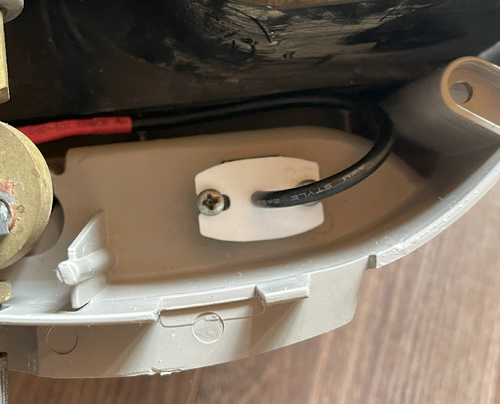
To try to answer your question, assuming you mean the Defender controller PCB, here is a photo with an "E2" label that matches your question. (The photo is from a wiki construction topic.)
The power connector "signal" is transformer isolated AC, so there is no polarity (positive or negative). The schematic shows connection to two full wave bridge rectifiers. Accordingly, there would be no "polarity" preference.
(For line voltage AC wiring, the equivalent designation is "hot" and "neutral." This is critical for lamp wiring where the lamp socket shell should be connected to neutral so that entire lamp does not become "hot" during periods of high humidity, contamination, deterioration, etc., resulting in a shock hazard, or a subtle vibrating sensation. The Zip cord wire with the ribbing or stripe is the neutral wire, and the other one is hot.)
The picture shows a Zip-like cord connection in which the outer (towards J4) conductor is ribbed. You might as well install the new cord into the pads like the picture, but it doesn't matter, because it is isolated low voltage AC.
BTW, you could use those "grass clips" (mentioned elsewhere) to place the power cord at ground level to avoid snagging the cord when walking or mowing.
New Connectors!?
Now, what is interesting to all on this forum with worn out or corroded connectors is: how did you obtain a new connector? The vendor and part number? Did this connector come with a cable? I think we all would like to replace our connectors, which have become intermittent over the last 15+ years. We are interested in both the male and female (which is which?). Thank you for your time.
|
Re: Defender Power Connector April 28, 2024 10:30PM | Registered: 24 days ago Posts: 6 |
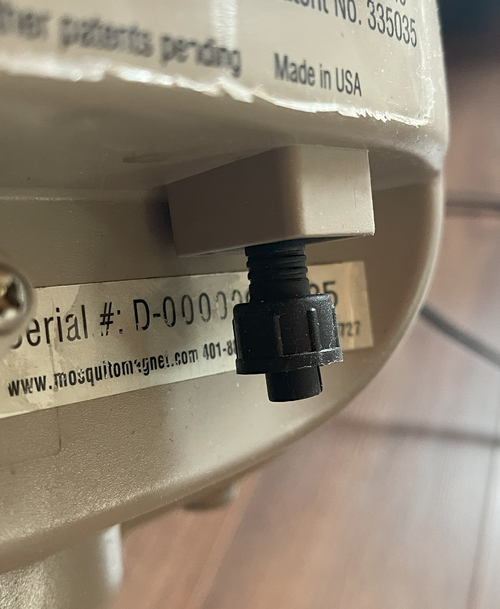
Yes, this is a board I possess. I've replaced the connectors and 3D printed a new holder that precisely matches the original shell. However, upon plugging in the board and turning it on, there's no response from the device. There's no blinking light and the fan isn't running. Is there another method to verify if the board is faulty? Alternatively, does anyone here specialize in repairing these boards? With mosquito season beginning, I'm eager to get the device operational again. thank you
|
Re: Defender Power Connector April 29, 2024 03:43PM | Admin Registered: 7 years ago Posts: 165 |
... I've replaced the connectors and 3D printed a new holder that precisely matches the original shell. However, upon plugging in the board and turning it on, there's no response from the device. There's no blinking light and the fan isn't running. Is there another method to verify if the board is faulty?
You can use a cheap voltmeter or oscilloscope to probe the board with power connected. Your issue is likely a simple failure of the board to get power from the power supply, maybe a faulty connection. Start with the disconnected cable from the power supply, connect a voltmeter set to AC, and look for ~15 volts AC. If Ok, connect it to the trap, and look for that same or somewhat lower voltage on the E1 and E2 pads.
If all looks Ok, then probe the outputs of the two bridge rectifiers D1 and D2. They produce DC voltages of about 20 volts (the peak value of the input AC voltage). There will be nearly none after D1 (because of the filter capacitor), and a lot of AC after D2 (no cap).
If all that looks Ok, I would suspect the switch. The contacts and leads are very fragile, easily damaged by disassembly, and the switch itself might be somewhat oxidized. You might just clip or solder together the switch terminals. (I don't really see the need to turn the trap off when it is so easy to disconnect the power, and that switch just inhibits the controller chip, it does not switch the power.)
If Ok, the next thing is to probe is the thermistor. There should be an AC signal there along with some DC. The AC signal indicates the controller chip is working.
Given that this failure is due to trauma and not deterioration, these steps are very likely to reveal the fault. Hopefully, they aren't too daunting.
...replaced the connectors and 3D printed a new holder....
Could you perhaps upload a photo or two, and the design file? I suppose you did that because you could not find a ready-made replacement? Thanks.
Alternatively, does anyone here specialize in repairing these boards?
Don't know, but we live in "disposable society" times. This site is one of many others that assist DIYers in fixing their own "stuff." Anyway, welcome to the wondrous world of trap troubleshooting!
|
Re: Defender Power Connector April 29, 2024 05:41PM | Registered: 24 days ago Posts: 6 |
Below is the file for an alternative power plug, provided in case it's needed. It's an STL file that can be loaded into any 3D printing slicing application and exported for your 3D printer. Please note that this file is for the old model of the Defender. I'm uncertain whether it will be compatible with newer Mosquito Magnet machines.
the plugs - Amazon (small size)
mm_plug.zip
the plugs - Amazon (small size)
mm_plug.zip
|
Re: Defender Power Connector May 03, 2024 11:49AM | Admin Registered: 7 years ago Posts: 165 |
...an alternative power plug...
The igniter draws significant current, however, the short length of #22 wire shouldn't be a problem. For future designs, the 18 gauge plug might be more robust and appropriate.
Edited 1 time(s). Last edit at 05/03/2024 12:00PM by dev.
The igniter draws significant current, however, the short length of #22 wire shouldn't be a problem. For future designs, the 18 gauge plug might be more robust and appropriate.
Edited 1 time(s). Last edit at 05/03/2024 12:00PM by dev.
Sorry, only registered users may post in this forum.

