Home
>
Mosquito Magnet
>
Topic
Liberty MM Conversion Project
Posted by Independence
|
Liberty MM Conversion Project August 23, 2020 01:29AM | Registered: 3 years ago Posts: 152 |
Ok, so I must be a sucker for punishment, but today I picked up a free Liberty MM. My goal is to convert it to spark ignition and also make a new WiFi controller for it. Kinda like a smaller Mk 2 version of my Independence. I'm surprised how much smaller it is compared to the Independence, almost like half the size. The fan also runs at a full 12V compared to the 9.7V or so of the Independence, so it may well suck in more mosquitoes than the battery/TEG powered versions.
So, the project starts with this first post and I don't know how long it will take, but I'll document it here for posterity. First of, I'm surprised how clean it was for such an old unit:
You can see the usual broken nylon screw on the thermistor.
The thermistor rod doesn't seem to have too much junk on it and the thermistor measures out correctly, so I think it will clean up nicely.
The igniter looks to be in good shape as well and glows nicely at about 12v and 2.5A. It will be a pity to destroy it to test it as a spark plug.
So, with a potentiometer as my thermistor, the unit appears to function correctly. 3 mins after turn on, the fan slows down for a few seconds and then sometime after that, the igniter turns on. At this point, the yellow LED is flashing but when I start to turn the pot down, it eventually stops flashing and turns solid. As I keep reducing the resistance, it eventually turns green, which is Run mode. The only issue is that the solenoid does not appear to be working.
(continued below)
So, the project starts with this first post and I don't know how long it will take, but I'll document it here for posterity. First of, I'm surprised how clean it was for such an old unit:

You can see the usual broken nylon screw on the thermistor.

The thermistor rod doesn't seem to have too much junk on it and the thermistor measures out correctly, so I think it will clean up nicely.

The igniter looks to be in good shape as well and glows nicely at about 12v and 2.5A. It will be a pity to destroy it to test it as a spark plug.
So, with a potentiometer as my thermistor, the unit appears to function correctly. 3 mins after turn on, the fan slows down for a few seconds and then sometime after that, the igniter turns on. At this point, the yellow LED is flashing but when I start to turn the pot down, it eventually stops flashing and turns solid. As I keep reducing the resistance, it eventually turns green, which is Run mode. The only issue is that the solenoid does not appear to be working.
(continued below)
|
Re: Liberty MM Conversion Project August 23, 2020 01:51AM | Registered: 3 years ago Posts: 152 |
I don't know if the solenoid clicks on the Liberty, but I heard nothing despite applying 12v directly to its terminals. In measuring it's resistance, it is 221 ohms. The solenoid on the Independence draws about 100ma, and at 221 ohms, this one only draws less than 60 ma. But it IS at 12V compared to the 9.7V of the Independence, so maybe it is correct. However, the solenoid doesn't appear to move, and this may be a show stopper as there would appear to be no way to get a replacement. The gas valve is completely different from the Independence and appears to use a diaphragm to shut off the gas. In looking at the solenoid itself, it appears to be stuck open and not able to move at all.
This is the valve with the solenoid and diaphragm removed. Nothing special.
The diaphragm is shown face up here, but the rubber stop in the center actually goes face down against the gas entry point. My assumption is the that solenoid plunger is spring loaded to press down on the diaphragm when it is off, and lifts off when it is on. However, I cannot get the plunger to move at all and I can't quite tell if it's open or closed.
The picture above would appear to show the solenoid retracted and not able to press down on the diaphragm at all. So gas would be flowing all the time.
So this is where I'm at right now. Without a working solenoid valve, it could be a very short project...
Edited 1 time(s). Last edit at 08/23/2020 01:58AM by Independence.

This is the valve with the solenoid and diaphragm removed. Nothing special.

The diaphragm is shown face up here, but the rubber stop in the center actually goes face down against the gas entry point. My assumption is the that solenoid plunger is spring loaded to press down on the diaphragm when it is off, and lifts off when it is on. However, I cannot get the plunger to move at all and I can't quite tell if it's open or closed.

The picture above would appear to show the solenoid retracted and not able to press down on the diaphragm at all. So gas would be flowing all the time.
So this is where I'm at right now. Without a working solenoid valve, it could be a very short project...
Edited 1 time(s). Last edit at 08/23/2020 01:58AM by Independence.
|
Re: Liberty MM Conversion Project August 23, 2020 02:28AM | Registered: 3 years ago Posts: 152 |
Hmm, in looking around, it appears that there are Liberty versions that use the newer valve and solenoid:
That valve assembly and solenoid looks like the same as my Independence:
The only difference is that the nozzle is directly attached on the Independence, while on the Liberty, a line is run to the nozzle. If the fittings are the same on the valve, then I could swap the solenoid and valve from my spare Independence.

That valve assembly and solenoid looks like the same as my Independence:

The only difference is that the nozzle is directly attached on the Independence, while on the Liberty, a line is run to the nozzle. If the fittings are the same on the valve, then I could swap the solenoid and valve from my spare Independence.
|
Re: Liberty MM Conversion Project August 23, 2020 02:23PM | Admin Registered: 7 years ago Posts: 164 |
Gee, good for you. I have one that a reader has inquired about converting a Liberty, but haven't modified it because of lack of time, I don't need it having 2 working traps already, and it is, or was, working as is. I would rather work on an Independence, which I could plant near the wetland area.
...solenoid retracted and not able to press down on the diaphragm...
You must set your plunger free. Try wiggling and rotation, "tapping," heat, chemicals, and disassembly, in order of destructiveness. I would favor disassembly in order to determine why it froze in the first place, which would be useful information. It must never stick, especially open. They say, "This is a lawsuit waiting to happen." A repair video on a public drive might be called for.
The Liberty uses, what, 4 sensors, while the Defender uses only the thermistor. I don't see any real need for the other sensors, since the thermistor can tell enough given some time, which has proven to be not critical. When the Liberty was developed, the designers took no chances, but apparently later concluded this was over-kill.
While modifying the system, how about adding connectors for the thermistor and solenoid? Plus a rigid catch basket to replace those creepy and horrifying nets that depend on a lobster trap style netting obstruction plus the kindness of mosquitos to prevent escape and subsequent bites when changing the net. And don't forget a mechanical (not momentary) on/off switch so that the trap runs after a power interruption?
I guess these shortcomings are some of the main reasons I have not jumped into my Liberty project. But good luck to you. Maybe I have to find time to work on mine, too...
|
Re: Liberty MM Conversion Project August 23, 2020 06:43PM | Registered: 3 years ago Posts: 152 |
> You must set your plunger free.
I wonder if this is why they went away from this valve design to the current design, i.e. unreliable. I notice ALL current designs uses the same type of valve now. I've taken the gas valve/solenoid from my spare Independence and have verified that the fittings all fit, so I should be able to use it in the Liberty. I just have to do some rework on the case to get the gas line out. Since I was scavaging, I will also use the igniter board from the Independence to initially provide spark ignition to the Liberty.
> The Liberty uses, what, 4 sensors, while the Defender uses only the thermistor. I don't see any real
> need for the other sensors, since the thermistor can tell enough given some time,
I agree. The later models also just depend on the thermistor indications for abnormal conditions. I won't be including those sensors.
>
> While modifying the system, how about adding connectors for the thermistor and solenoid?
Those pads are actually on 0.1" spacing so you can easily add headers for connectors. In fact, later boards have connectors for the thermistor.
> Plus a rigid catch basket to replace those creepy and horrifying nets that depend on a lobster trap style
Ha ha, that's why they designed the Patriot... I could design and 3D print a net housing, but couldn't easily do the netting. I would have ideally wanted to modify a Patriot, but you can't pick what you get for free...
> And don't forget a mechanical (not momentary) on/off switch so that the trap runs after a power interruption?
Not modifying the housing, but it is easy to make it just always power on in an ON state, regardless of the state of the momentary switch. My Independence powers back on after a power outage, but it has safeguards that checks the thermistor temperature first. If the temperature is above a certain number, it runs in fan mode until it drops to a set temperature, and then it initiates a normal start cycle.
> I guess these shortcomings are some of the main reasons I have not jumped into my Liberty project. But good luck to you.
I kind of like the compact form factor of the Liberty. Since my main MM doesn't need battery operation, I might as well run a modified Liberty, as long as it has all the same functions as my current Independence.
|
Re: Liberty MM Conversion Project August 24, 2020 01:34AM | Registered: 3 years ago Posts: 152 |
I've had a chance to run the Liberty on the bench and wanted to run my findings by other Liberty owners. It doesn't quite behave like my Independence so I just want to make sure it is the correct behavior.
Upon pressing the ON button, the fan comes on full speed and the yellow warm up LED starts flashing. After just over 3 minutes of this, the igniter and solenoid gets turned on, pretty much at the same time. The fan remains on full speed, though it does dip a bit in speed a bit due to the volt drop when the igniter kicks in (I'm running it on a 13.5V DC supply since I don't have the original transformer).
From here, I can reduce the thermistor resistance via my potetiometer, until it gets to about 45.6K, which is about 55C, At this point, the warm up LED stops flashing and goes solid. I guess it's getting up to temperature. However, the igniter is STILL turned on and glowing away.
When I reduce the resistance to about 11.2K, which is about 93C, the warm up LED goes off and the green Run LED comes on solid. I guess it has reached operating temperature and it finally shuts the igniter off.
This next point probably isn't too accurate but when I reduce it to about 1.39K or 166C, the unit appears to reset to the warm up state again. It didn't indicate a fault, which surprised me. I'll have to investigate this high temperature threshold a bit more.
So, my question is whether this is the normal behavior of a Liberty and WHY IS THE IGNITER LEFT ON until the unit reaches Run mode? I used a pot, so could advance it fairly quickly, but I imagine this could take at least 10-15 minutes in real time. I haven't hooked up gas to the unit yet as I'm not sure the Independence regulator will work with the Liberty. They are both supposed to be 11" WC, but they are totally different looking regulators. The Independence also uses a 1.75 GPH nozzle while the Liberty has a 1.5 GPH nozzle, so there could be slight differences, given that both are supposed to last 21 days on a tank. The solenoid should work though, and I'm just waiting for an adapter to be able to use the original regulator with the new solenoid.
I DID hook up the Independence igniter board to the Liberty controller board. Basically connected the V+ of that board to +5V on the controller board, and the Igniter pin to the MOSFET pull down. It activated it fine that way, but I can't see letting the OEM controller keep the igniter on for so long. I have not tried sparking into the chamber yet (Dev, last chance to swap a good igniter for a bad one!) as that requires me to destroy a perfectly good igniter.
Anyway, if I could get some confirmation of the Liberty behavior, I would appreciate it. In particular, I would like to know the relevant thermistor temperatures for each stage and the range for normal operation, as well as the over temperature value. I have some rough values but others have had more experience with it here. I plan on using the same two stage ADC method as on the Independence since that provides better resolution at the higher temperatures.
My next goal is to get it up and running in it's original form so I know it's working properly, and then test out the spark ignition.
|
Re: Liberty MM Conversion Project August 24, 2020 01:14PM | Admin Registered: 7 years ago Posts: 164 |
Anyway, if I could get some confirmation of the Liberty behavior, I would appreciate it.
The wiki has some information regarding timings. The solenoid and igniter states are not documented there. If you have those, I (or you) can add it to the wiki.
The timings table shows the fan slowing for about 5 seconds. This is a very short time, and, unlike in the Defender where this is prolonged and caused by the fan running at a 25% PWM duty cycle, I now realize is possibly because of the voltage drop in the low voltage power supply cable and power transformer. This could occur because the igniter is about 1 ohm when cold, and could draw about 9 amps from a "stiff" fixed supply when first starting. The combined impedance helps to avoid a large current inrush to the igniter, which is less of a mechanical shock, a killer of components. A reader who substituted a fixed voltage power supply suffered from repeated igniter failure before adding a soft start.
The 5 seconds mentioned in the table corresponds roughly to the time it takes the igniter to warm up to where it is not drawing so much current and dragging down the power supply line. However, I don't remember a gradual fan speed increase that would match the declining current draw of the warming igniter. You can measure the fan voltage with a scope to see what's happening.
Reduced air flow was evidently recognized as beneficial in the Defender startup. However, the Liberty's 5 seconds is too short to benefit starting because the igniter is not hot enough to ignite the propane until after this time.
You would think that the igniter would go off after a certain temperature rise, like the amber light switching from flashing to solid, but no. I don't think that is a bug or fault, but part of the design. The designers might have a observed a problem with incomplete combustion during warm up that increased ignition time addressed. The Defender had an intermittent "abnormal combustion" issue last year that took a long time to solve. Also, once the igniter has reached a reasonable temperature, it is not that harmful to it to keep it on for a while. The most stress occurs with temperature cycling.
My next goal is to get it up and running in it's original form so I know it's working properly, and then test out the spark ignition.
Good luck!
BTW Is it possible to document and repair your original propane valve? As you have a problem with it, so do many others who lack spare parts. Otherwise, source is needed for replacement valves.
...last chance to swap a good igniter for a bad one!
Thanks, but I need the failed one for experimentation with that off-the-shelf grill igniter. Also, your Independence spark igniter seemed to have just a single electrode, that looks a lot like the silicon nitride igniters but with a single thickly insulated wire. Perhaps you could feed your working igniter with the high voltage, and it would work as is without trying to balance the arc between the electrodes.
Edited 1 time(s). Last edit at 08/24/2020 01:19PM by dev.
|
Re: Liberty MM Conversion Project August 24, 2020 04:09PM | Registered: 3 years ago Posts: 152 |
> The wiki has some regarding timings.
I did see those, but the temperatures were in terms of the thermistor voltage measurement scheme, which I didn't take the trouble to decipher since I wasn't going to be using it. I need those translated into thermistor resistance or temperature so I can use them as a reference in my implementation.
> The solenoid and igniter states are not documented there. If you have
> those, I (or you) can add it to the wiki.
They basically both turned on at the 3 min mark... and the igniter turned off when the Run LED came on.
> The timings table shows the fan slowing for about 5 seconds. This could occur because the igniter is
> about 1 ohm when cold, and could draw about 9 amps from a "stiff" fixed supply when first starting.
This is EXACTLY what happens with the igniter. I see an initial rush of current and as it heats up, the current drops down to about 2-2.5A. I observed the fan PWM input and it never changed from being fully on and any drop in fan speed is totally due to the input voltage dropping below 12V into the 12V regulator. Since I don't have an original transformer, I don't know if it was sized to allow for this drop in fan speed and is by design. This is another unknown variable as I proceed onwards into trying to get it to run.
> However, the Liberty's 5 seconds is too short to benefit starting because the igniter is
> not hot enough to ignite the propane until after this time.
That's a good point, so it's likely not by design. The Independence slowing down the fan prior to turning on the gas, coupled with it's spark ignition has been extremely reliable. I think others have said the Liberty and Defenders ignite with a hard 'pop'? The Independence ignites with a soft muffled 'poof', kinda like how a gas stove ignites. That may be a function of the hot-surface vs spark igniter. So I can do some experimentation with fan speed when I try spark ignition on the Liberty.
> Thanks, but I need the failed one for experimentation with that off-the-shelf grill igniter.
Ok, I thought you had several failed OEM igniters, but I guess they were the replacement ones, not the OEM ones. BTW, what happens when they fail? Do they just fail to glow?
> Also, your Independence spark igniter seemed to have just a single electrode, that looks a lot like the
> silicon nitride igniters but with a single thickly insulated wire. Perhaps you could feed your working igniter with
> the high voltage, and it would work as is without trying to balance the arc between the electrodes.
I could try it, but on the Independence, the case of the cat converter is a single aluminium piece and the other end of the igniter is connected to it. So the single electrode sticking through the case can easily spark to the inside shell of the converter. On the Liberty, the cat converter appears to be a separate metal tube that sits inside the aluminium casing, with possibly some RTV material in between. So the electrode may not spark to the inside of the cat converter. One thought is to tap a hole in the side of the aluminium casing for a screw to contact the cat converter electrically, and then connect the return lead to this screw. Technically, I should try this BEFORE I destroy the working igniter, but I am loathe to disassemble the cat converter since it looks really clean inside. Hopefully you will have tested your igniter before I get to this point...
> BTW Is it possible to document and repair your original propane valve? As you have a problem with it, so do many others who
> lack spare parts. Otherwise, source is needed for replacement valves.
There WAS no repair, but I will post something on how the newer valves can be used on older units. The newer valve looks more repairable as well compared to the old one.
|
Liberty MM old solenoid valve options? August 24, 2020 06:25PM | Registered: 3 years ago Posts: 152 |
So, while trying to document the old valve, it started working! Here's a recap of the valve:
It is a diaphragm based valve. I had assumed that a spring loaded plunger in the solenoid kept the diaphragm pressed against the gas orifice until it was engaged. However, in applying power to the solenoid, I never heard any clicks or movement and the solenoid only consumed 60 mA of current. I thought the metal in the center of the solenoid was a plunger. However, I could never get any movement out of it. Now, in hindsight, after having cut the valve out, it dawns on me that I should have tested it for magnetism. As I assembled the valve to take some pictures, I tried applying power one more time. This time I heard a slight click. Long story short...
Yes, the solenoid was just supposed to pull the diaphragm up to open the valve using that center magnetic piece. Why it didn't do it numerous times before and started doing it now, I don't know. It always consumed the same current, so the magnetism must always have been there, so I don't know why the diaphragm didn't engage. In retrospect, I should have tested it for magnetism in the first place. One of those senior moments...
Anyway, I was going to show how current solenoid/valves could be used in the Liberty, since newer versions seem to use those valves, so I guess it's still relevant, even though my original valve appears to be working now.
The valve on the right is the original Liberty valve, cut out of the case (argh.. ). Regulated propane comes in from the bottom, and is released by the diaphragm valve into the chamber where the Schrader valve is, as well as the fitting to the nozzle. The valve on the left is from my Independence. I'm not sure what type of valve it is as I've never dismantled it completely, but it appears to be the same type of valve used in all current MMs. The Schrader valve is on the left and the nozzle housing is screwed directly into the valve. The nozzle housing, with the nozzle, is then inserted and fastened into the carburetor opening.
(contd...)
Edited 2 time(s). Last edit at 08/24/2020 07:53PM by Independence.

It is a diaphragm based valve. I had assumed that a spring loaded plunger in the solenoid kept the diaphragm pressed against the gas orifice until it was engaged. However, in applying power to the solenoid, I never heard any clicks or movement and the solenoid only consumed 60 mA of current. I thought the metal in the center of the solenoid was a plunger. However, I could never get any movement out of it. Now, in hindsight, after having cut the valve out, it dawns on me that I should have tested it for magnetism. As I assembled the valve to take some pictures, I tried applying power one more time. This time I heard a slight click. Long story short...

Yes, the solenoid was just supposed to pull the diaphragm up to open the valve using that center magnetic piece. Why it didn't do it numerous times before and started doing it now, I don't know. It always consumed the same current, so the magnetism must always have been there, so I don't know why the diaphragm didn't engage. In retrospect, I should have tested it for magnetism in the first place. One of those senior moments...
Anyway, I was going to show how current solenoid/valves could be used in the Liberty, since newer versions seem to use those valves, so I guess it's still relevant, even though my original valve appears to be working now.

The valve on the right is the original Liberty valve, cut out of the case (argh.. ). Regulated propane comes in from the bottom, and is released by the diaphragm valve into the chamber where the Schrader valve is, as well as the fitting to the nozzle. The valve on the left is from my Independence. I'm not sure what type of valve it is as I've never dismantled it completely, but it appears to be the same type of valve used in all current MMs. The Schrader valve is on the left and the nozzle housing is screwed directly into the valve. The nozzle housing, with the nozzle, is then inserted and fastened into the carburetor opening.
(contd...)
Edited 2 time(s). Last edit at 08/24/2020 07:53PM by Independence.
|
Re: Liberty MM old solenoid valve options? August 24, 2020 06:43PM | Registered: 3 years ago Posts: 152 |

You can see that the nozzle fitting of the Independence detaches from the valve. That nozzle fitting is the same fitting used on the Liberty to pipe the propane to the remote nozzle. So you could essentially replace the fitting and replicate how the Liberty valve looks like:

If you want, you could also remove the direct Schrader valve and replace it with the remote fitting for the Liberty, but since I never use the valve, I would't bother. It's probably more effective to just clean your nozzle manually each year.
Once you replace the nozzle with the fitting, it should fit in the Liberty. The wildcard is that while the solenoid and valve should work, you should make sure you have the same regulator as before. My original Liberty hose had a 1/4" NPT male fitting towards the regulator, and a non-removable fitting on the valve. To use the same regulator on the new valve, you would need a 1/4" MNPT to 1/8" MNPT hose. Your mileage may vary since there may be other types of regulators out there.
It was also impossible to remove the original hose and valve without cutting it out. The 1/4" NPT fitting will not fit through the case hole. I actually drilled around the case to get it out, and I will have to 3D print something to clamp the new hose down to the case.
So that's my little solenoid adventure. If I had done my work correctly, I might have got to a working solenoid without having to cut it out. But my mistake is your benefit... :)
|
Independence igniter vs Gas grill igniter August 24, 2020 07:47PM | Registered: 3 years ago Posts: 152 |
Here are some animated GIFs to show the difference between the Independence igniter and the cheap gas grill igniter. In both cases, they are sparking via the Liberty OEM hot surface igniter. First, the Independence igniter board:
The Independence board has a 1.5uF capacitor and produces a pretty decent spark across quite a distance.
And now the cheap $9 gas grill igniter:
I was surprised... it's no slouch and with just a 1.5v battery, generates a pretty decent spark too. It appears to be potted on the bottom, but the battery compartment is not, so hopefully the whole top of the board is not potted. It looks like a pretty decent candidate as the igniter for the Liberty project...

The Independence board has a 1.5uF capacitor and produces a pretty decent spark across quite a distance.
And now the cheap $9 gas grill igniter:

I was surprised... it's no slouch and with just a 1.5v battery, generates a pretty decent spark too. It appears to be potted on the bottom, but the battery compartment is not, so hopefully the whole top of the board is not potted. It looks like a pretty decent candidate as the igniter for the Liberty project...
|
Re: Liberty MM old solenoid valve options? August 25, 2020 12:13AM | Admin Registered: 7 years ago Posts: 164 |
I need those translated into thermistor resistance or temperature
Right. Those measurements are from the scope as the unit switches in different value resistors, which is all I expected anyone would want, dealing with a stock trap. I didn't record the resistor drive waveforms, and the PIC might switch a different resistor in turn, or two or more may be on at the same time. But this resistor drive pattern surely must match yours, so you can calculate the resistance, given a few extra hours or days of work...
... original transformer, I don't know if it was sized to allow for this drop in fan speed and is by design. ...
That's a good point, so it's likely not by design.
I believe it is by design (and to reduce cost, an important aspect of the design, unless you are lucky enough to work in a field where cost is no object. Is there such a field?). The impedance of the transformer and the long low voltage zip cord line itself limits the inrush current to reduce the inrush current so the igniter lasts longer. The steady state current is limited by the reduced RMS voltage provided by the large rectifier not followed by a capacitor. As mentioned before, my Fluke measures about 9 volts average (not RMS) when hot.
BTW, what happens when they fail? Do they just fail to glow?
Some go open circuit, meaning no conduction, and of course these fail to glow. Recent failures have been in the "not hot enough" category. They are not open, and measure cold the same as new ones, but they just don't get hot enough (red but not enough hotter yellow). Maybe they are not bad at all, but rather something else is causing trouble that gets fixed when replacing the igniter with a new one. That's part of what makes this project so much fun.
...cat converter appears to be a separate metal tube that sits inside the aluminum casing, with possibly some RTV material in between.
The catalytic converter tube has some adhesive on one side in some units (not mine), but it is in electrical contact with the metal case.
... original Liberty valve, cut out of the case ...
Yeah, I hate causing permanent disfigurement like that. That hose connection looks like a crimp of a barrel sleeve around a barb fitting, nicht wahr? I know this is not an authentic antique automobile or a Stradivarius violin, but maybe you can just use the original part after carefully expanding the crimp barrel, removing the cut hose, and re-crimping. Good luck with that...
.. nozzle fitting of the Independence detaches from the valve.
Good to know. I didn't dare trying to unscrew the valves I have, but now I can try (next year, anyway).
|
Re: Independence igniter vs Gas grill igniter August 25, 2020 02:08AM | Registered: 3 years ago Posts: 152 |
I broke apart the case of the cheap igniter and here's how it compares to the Independence igniter:
Far less components. It has a 0.68uF capacitor, and the SIDAC is a 220v device, compared to the 1.5uF capacitor and 150V SIDAC in the Independence. In measuring it's operating characteristics, the device consumes like 150 mA at 1.5V while sparking. The bigger issue, however, is that the HV side does not appear to be isolated from the low voltage side. The device actually sparks from the igniter terminal to the +ve of the battery terminal! Unfortunately, the bottom of the unit is potted and I only found that out by buzzing it out after getting some little shocks (see the latex glove in the animated GIF?). I don't think I will be connecting it to any controller anytime soon...
Bummer, at this point, since I can't use it as-is, I'm thinking of de-potting it and harvesting the key transformers and capacitor and see if I can redesign it like the Independence version using those components. The HV transformers appears to be the same radius but the cheap one is about 50% taller. Hopefully, I can remove it from the case and potting without destroying it. My fear is that it is an auto-transformer instead of an isolating transformer, which would explain the lack of isolation and would also suck....
|
Re: Liberty MM old solenoid valve options? August 25, 2020 02:34AM | Registered: 3 years ago Posts: 152 |
> But this resistor drive pattern surely must match yours, so you can calculate the
> resistance, given a few extra hours or days of work...
I already know the rough values from using my pot, but was hoping someone had already recorded all the transition points. I can just go through it more precisely with the pot again. It seems to take several seconds for the PIC to read the thermistor, so it's kind of a tweak, wait, tweak, wait. process. And there's that stupid 3 min startup wait! Every time I pass a transition point, I unplug the pot to measure it, and of course the Liberty faults out and I have to restart it again, with the 3 min wait!
>
> I believe it is by design.... limits the inrush current to reduce the in rush current so the igniter lasts longer.
I meant that the fan reducing speed was not by design, since they were designing for the above...
> The catalytic converter tube has some adhesive on one side in some units (not mine),
> but it is in electrical contact with the metal case.
I should be able to test the sparking with the Independence igniter and the OEM igniter then....
> Yeah, I hate causing permanent disfigurement like that. That hose connection looks like a crimp of a
> barrel sleeve around a barb fitting, nicht wahr?
Initially, I was trying to remove the hose without cutting it, but as mentioned, the NPT fitting on the regulator wouldn't fit through the barrel. At that point, I wanted to keep the hose intact, so I sacrificed the barrel. I will be able to 3D print a new barrel and fastener. Of course, later, when I thought the valve was terminal and I had to switch to the Independence valve, I then cut the hose. *Sigh* If only I could re-do that whole part again......
|
Re: Liberty MM old solenoid valve options? August 25, 2020 11:43PM | Admin Registered: 7 years ago Posts: 164 |
Every time I pass a transition point, I unplug the pot to measure it, and of course the Liberty faults out and I have to restart it again, with the 3 min wait!
It might be easier to measure the drive Vi to each of the resistors (1 out of 4), use the single (and/or the parallel if more than one resistor is driven at a time) drive resistance Rd for each step, then calculate the thermistor resistance Rt from the thermistor voltage Vo. If my algebra is accurate, this is Rt = Rd * Vo / (Vi-Vo). This assumes the undriven inputs are floating and not grounded.
That 3 minute wait is really annoying. However, sometimes it takes that long for the Defender to cool down to a low-enough temperature to detect combustion from a temperature rise when restarting after a momentary power interruption.
... I sacrificed the barrel. I will be able to 3D print a new barrel and fastener.
Oh, sorry, I meant the ferrule that crimps the hose to the valve input fitting. Using a hose clamp instead of a professionally crimped ferrule is more or less universally not recommended.
Sorry to hear about spark conduction back to the input side of the igniter. Can you measure a resistive connection?
|
Re: Liberty MM old solenoid valve options? August 26, 2020 04:09AM | Registered: 3 years ago Posts: 152 |
> Sorry to hear about spark conduction back to the input side of the igniter. Can you measure a
> resistive connection?
Yes, it's basically zero ohms between the +ve of the battery and the spark return point.
Did you buy the unit in the Amazon picture? I ended up buying a cheaper $9 version. I wonder if they are all the same design. BTW, I think that Amazon picture was deceptive. It appears to show two leads that go to electrodes that spark against each other. But based on my unit, I believe those are supposed to be independent electrodes to different burners and are designed to spark to ground, which is an electrical connection on the unit under the screw cap.
Anyway, I did a test today using the Independence igniter board and the OEM igniter. I verified that the cat converter case DID have electrical connection to the aluminum case, so I stuck the igniter in its hole and grounded the spark return to the case. You can hear some light sparking inside, but I have no way of telling where it's sparking to. So I decided to just try it out by hooking the igniter board to the Liberty controller via that FET and bypassing the IGNL input. The first time it went through the cycle, it took several minutes of sparking AFTER the gas was turned on before I detected any rise in temperature. The 2nd time I tried it, I didn't get a rise after 5 minutes so I stopped it.
I guess I did it in reverse order as I just wanted to see if the igniter would work as-is, but since it didn't consistently, I then restored the hot-surface igniter and characterized the normal behavior, as I had not yet tested it since I got it. I metal taped a thermocouple temperature probe with heat sink compound right next to the thermistor just to get a rough idea of the temperatures. Here's what I got:
Ambient temp: 85F
Initial probe temp: 34C
At 3:05m, the igniter and gas is turned on
About 30 seconds later, the probe temperature rose to 35C, so I had ignition
At 6 minutes, the temperature hit 70C and the Yellow LED turned steady
At 8 minutes, the temperature hit 107C, and the Green Run LED turned on.
After about 15 minutes, it appears to be leveling off at about 128C
It may get a little hotter, but I stopped the test at this point. I was able to repeat it after cool down, with similar results, so that's kinda my initial basis until I get my own controller on that thermistor and get to compare results.
I was surprised that I never heard any ignition sounds, no 'poof' or 'pop'. I'm used to being able to hear it on the Independence, but that fan is running slow during ignition, while the Liberty's fan is running loudly at full blast. The only indication I had of ignition was the temperature rise and that characteristic smell. I was also surprised that ignition happened so fast after the igniter and gas was turned on, less than 30 seconds. But at least now I have an idea of how the Liberty works and how long it takes to ignite, pass through its stages, and get to temperature.
Now that I know my Liberty is working properly, I will next focus on getting the igniter to spark properly inside the chamber. The OEM igniter could produce a great spark to the outside of the chamber but is evidently not sparking well inside the chamber. I will have to come up with something, with the last resort being to split the tip of the hot-surface igniter.
|
Initial measurements from original Liberty, with hot surface igniter August 26, 2020 02:02PM | Registered: 3 years ago Posts: 152 |
Just for the record, here are the measurements from my first run, with the chart overlayed with both runs.

|
Re: Liberty MM old solenoid valve options? August 26, 2020 02:11PM | Admin Registered: 7 years ago Posts: 164 |
Did you buy the unit in the Amazon picture? I ended up buying a cheaper $9 version. I wonder if they are all the same design.
I bought the one you recommended. It has two independent electrodes that have no DC continuity to the ring battery connection terminal, or to each other, which almost impossible for me to believe, shocking really. The good news is that the two electrodes arc to each other, and the balanced drive might not interfere too much with nearby circuitry if kept strictly symmetrical and parallel. The bad news is that the arc is pretty weak, and didn't light my propane torch. I haven't yet measured the RFI spectrum.
...an electrical connection on the unit under the screw cap.
Yeah, I didn't want that. This type will require the battery, high voltage (e.g., fiber optic) drive isolation, very short ignition and ground return wiring, and physical distance away from any sensitive electronics. Typical opto-isolators generally don't survive these high voltages.
The 2nd time I tried it, I didn't get a rise after 5 minutes so I stopped it.
Apparently, the spark gap is a critical parameter. See this pdf paper for theory, and this DIY article for more practical recommendation which says, in part, "a sideburner electrode should be suspended in the air 3/8″ from the burner."
...ignition happened so fast after the igniter and gas was turned on, less than 30 seconds.
The igniter takes about 10+ seconds to heat up and start initial ignition. Add another 20 seconds for the heat to build up and travel down the probe to the metal block then to the thermistor and to the probe. Whether or not all the air/fuel mixture is burning at that point, I don't know. The designers kept the igniter on regardless of initial ignition; there must have been a reason for that.
the last resort being to split the tip of the hot-surface igniter.
The gap size may not be optimal or even adequate. Can you fabricate something with a larger, adjustable gap? The Independence seems to have a long ceramic insulator. Can you see the spark destination? I doubt it is intended to arc back over the insulator to the case, it likely arcs across to the other side, or to some metal inside the catalytic converter. What is that arc dimension? Their igniter is likely optimized for that sized gap.
Edited 1 time(s). Last edit at 08/26/2020 02:16PM by dev.
|
Re: Liberty MM old solenoid valve options? August 26, 2020 03:04PM | Registered: 3 years ago Posts: 152 |
> I bought the one you recommended. It has two independent electrodes that have no DC continuity
> to the ring battery connection terminal, or to each other
Have you tried sparking from each electrode to the 'ground' connection on the battery barrel? I've seen other similar igniters on Amazon that have up to 4 electrode connections, and they all appear to be designed to spark to that connection. However, the fact that there was no electrical connection between your electrodes may indicate they are on separate and isolated HV windings? That would be good news compared to my unit.
> Can you fabricate something with a larger, adjustable gap?
That is what I'm planning to do. It won't be able to tolerate the high temperatures but should be sufficient to test ignition points.
> The Independence seems to have a long ceramic insulator. Can you see the spark destination?
> I doubt it is intended to arc back over the insulator to the case, it likely arcs across to the other side,
> or to some metal inside the catalytic converter. What is that arc dimension?
The Independence igniter extension is about 1" long. The cat chamber thickness is about 1/4" and there is a spacing washer on the outside, so I would guestimate that it extends inside slightly less than 3/4". I don't have measurements of the arc but from the pictures and memory, would guestimate that the inside diameter is about 2". I can't really look inside the hole enough to see if there is other metal for it to arc to. However, I think you can peek in through the ceramic honeycomb from the carburetor side to see where it sparks to (in the dark). That would require some disassembly and bench work though, and I'm not inclined to spend the time on it.
|
HV Generator Module August 26, 2020 09:42PM | Admin Registered: 7 years ago Posts: 164 |
There are several HV generator kits available on ebay (and amazon). They take forever to arrive. I just ordered one for $4.58 with free shipping arriving between 9/27 and 11/13.
Here is the link. This module appears to have two FETs, 3 chips, plus two HV resistors on the output and 2 caps (100 pf and 1000 pf), for a somewhat adjustable pre-loaded balanced output. Removing the 1000pf cap makes it into a "high temperature ignition type." They say the HV section should be coated in paraffin (ha) or epoxy or something easier to remove. It can run on 9-12 volts.
Another possibility is this simpler generator. Similar units are available, and some advertise they can burn through paper. These units must be loaded, but don't come with an arc gap to handle disconnection.
|
Re: HV Generator Module August 27, 2020 06:54PM | Registered: 3 years ago Posts: 152 |
> There are several HV generator kits available on ebay (and amazon).
Nice find. I like the one you ordered, compared to the 2nd one. That 2nd one consumes 2A at the input while the one you purchased is listed at a more reasonable 0.2-0.5A. They are still considerably more than the 20-30ma of the Independence board.
The more I think about it, replicating the original Independence design might be best since they designed an optimal unit for ignition. The issue is whether I can find close enough transformers, especially the HV one. The one in your unit looks identical to the Independence one, though who knows if the characteristics are the same.
The other option I'm now considering is the PWM soft start design mentioned in the Defender Arduino thread. If that really preserves the igniter, it might be a simpler option. I would still turn it off earlier, upon ignition detection. I will investigate it but will also continue to explore the spark ignition option.
BTW, maybe it's been noted elsewhere before, but I noticed two minor errors in your Liberty schematic on the Wiki:
1) The igniter MOSFET is labeled Q2 when it is actually Q3
2) The rectifier bridge for the 12V supply is mis-oriented
Edited 2 time(s). Last edit at 08/27/2020 07:04PM by Independence.
|
Re: HV Generator Module August 28, 2020 09:50PM | Admin Registered: 7 years ago Posts: 164 |
...now considering is the PWM soft start design...
That topic was introduced last October, and a reader who had gone through several igniters with his 2 cycles per day design implemented it, and he reported that the igniter has so far kept going, a great improvement. This is especially important if you are not using the original power supply, as he was not, because the original limited the inrush current to the cold igniter. Based on his results, you can install the working igniter and be done with the issue, even with a stiff power supply.
However, why not order a few of those marvelous $4.58 sparkers? With their full complement of semiconductors, it puts the MM unit to shame. But the HV section does need an insulating coating to work reliably under high humidity conditions. Perhaps a fairly thick silicone conformal coating would do. Unlike epoxy, something that can be removed for tweaks.
Thanks for the Liberty schematic corrections. I will update the schematic, but I have to find the source first and remap the component library symbols to the newest libraries, which could result in yet more errors...
|
Liberty Schematic Rev 0.1 August 29, 2020 01:10AM | Admin Registered: 7 years ago Posts: 164 |
A revised and higher resolution version of the Liberty schematic has been uploaded to the Liberty wiki topic.
|
Tests with soft-start igniter and simple implementation... August 30, 2020 09:40PM | Registered: 3 years ago Posts: 152 |
> This is especially important if you are not using the original power supply, as he was not,
> because the original limited the inrush current to the cold igniter. Based on his results, you can
> install the working igniter and be done with the issue, even with a stiff power supply.
Yes, if the soft-start igniter can be as reliable and as long-lasting as the spark igniter, I'm more than happy to go that direction. I can always design my new controller board with the soft start on the OEM igniter, but it can easily be modified to drive an external spark igniter.
I made up this circuit in a breadboard and tested it out:
It is basically an intercept circuit for the IGN line from the current PIC. The dotted line block would be inserted inline with the IGN line. The device is an ATtiny85 8 pin DIP microcontroller, which I am using to implement the soft start as well as an early turn off of the igniter. It basically intercepts the IGN from the PIC and when that signal turns on, it starts a PWM sequence out towards the igniter MOSFET. Right now, I have a simple linear ramp over about 5 seconds. This rather small animated GIF below shows the results:
Sorry for the small picture but it had to fit in 2MB. The left DVM shows the input voltage to the igniter, the right DVM shows the current, and the scope shows the output of the ATtiny85 into the MOSFET. You can see when I ungrounded the IGN input pin (has internal pullup), the PWM signal started to increase in width to the MOSFET. The soft start appears to limit the maximum current to about 2.2A. A cold hard start can result in up to 9.5A, which can't be good for the igniter. The ramp was a simple 0 to 255 increment, in 5 count increments every 200 ms, resulting in a a 5 second ramp to full on. You can see that it doesn't really start to glow until fairly close to the end, though these is some slight delay in the digital scope display. I'm using a 10A 13.5V power supply, so it is quite 'stiff'. The ATtiny85 program also shuts of the igniter after 45 seconds.
This worked well on the bench, so it was tested in the Liberty, in 'dead-bug' mode:
The chip was just double-sided onto the Liberty board and wired in. It needs just 4 connections, +5V, GND, IGN in and IGN out. I did have to cut a trace to intercept the IGN line, but since I intend to replace the controller anyway, it's not a big deal. You also have to spoof the IGNL line low so the PIC is happy. I just grounded the output of U5D.
I tested this setup 4-5 times and it hasn't failed to start up yet. It does take an extra 4-5 seconds for a detectable temperature rise, but that is to be expected, given the 5 second ramp. 45 seconds before shutoff might be a bit short, particularly as it starts when IGN is first detected. I will probably increase this time to about a minute, but so far in my tests, it hasn't failed to ignite. I am also thinking of modifying the PWM profile, such as maybe holding it longer at the lower current before ramping it up, instead of just a linear ramp up profile.
So, even if you intend to keep using your OEM controller, it might be worthwhile to insert something simple like this to prolong the life of your hot-surface igniter. It's simple enough to implement and doesn't require much modification.
> Thanks for the Liberty schematic corrections.
No, thank you for producing it in the first place. Saves me a lot of time in not having to trace it out.
Edited 1 time(s). Last edit at 08/30/2020 10:33PM by Independence.
> because the original limited the inrush current to the cold igniter. Based on his results, you can
> install the working igniter and be done with the issue, even with a stiff power supply.
Yes, if the soft-start igniter can be as reliable and as long-lasting as the spark igniter, I'm more than happy to go that direction. I can always design my new controller board with the soft start on the OEM igniter, but it can easily be modified to drive an external spark igniter.
I made up this circuit in a breadboard and tested it out:

It is basically an intercept circuit for the IGN line from the current PIC. The dotted line block would be inserted inline with the IGN line. The device is an ATtiny85 8 pin DIP microcontroller, which I am using to implement the soft start as well as an early turn off of the igniter. It basically intercepts the IGN from the PIC and when that signal turns on, it starts a PWM sequence out towards the igniter MOSFET. Right now, I have a simple linear ramp over about 5 seconds. This rather small animated GIF below shows the results:

Sorry for the small picture but it had to fit in 2MB. The left DVM shows the input voltage to the igniter, the right DVM shows the current, and the scope shows the output of the ATtiny85 into the MOSFET. You can see when I ungrounded the IGN input pin (has internal pullup), the PWM signal started to increase in width to the MOSFET. The soft start appears to limit the maximum current to about 2.2A. A cold hard start can result in up to 9.5A, which can't be good for the igniter. The ramp was a simple 0 to 255 increment, in 5 count increments every 200 ms, resulting in a a 5 second ramp to full on. You can see that it doesn't really start to glow until fairly close to the end, though these is some slight delay in the digital scope display. I'm using a 10A 13.5V power supply, so it is quite 'stiff'. The ATtiny85 program also shuts of the igniter after 45 seconds.
This worked well on the bench, so it was tested in the Liberty, in 'dead-bug' mode:

The chip was just double-sided onto the Liberty board and wired in. It needs just 4 connections, +5V, GND, IGN in and IGN out. I did have to cut a trace to intercept the IGN line, but since I intend to replace the controller anyway, it's not a big deal. You also have to spoof the IGNL line low so the PIC is happy. I just grounded the output of U5D.
I tested this setup 4-5 times and it hasn't failed to start up yet. It does take an extra 4-5 seconds for a detectable temperature rise, but that is to be expected, given the 5 second ramp. 45 seconds before shutoff might be a bit short, particularly as it starts when IGN is first detected. I will probably increase this time to about a minute, but so far in my tests, it hasn't failed to ignite. I am also thinking of modifying the PWM profile, such as maybe holding it longer at the lower current before ramping it up, instead of just a linear ramp up profile.
So, even if you intend to keep using your OEM controller, it might be worthwhile to insert something simple like this to prolong the life of your hot-surface igniter. It's simple enough to implement and doesn't require much modification.
> Thanks for the Liberty schematic corrections.
No, thank you for producing it in the first place. Saves me a lot of time in not having to trace it out.
Edited 1 time(s). Last edit at 08/30/2020 10:33PM by Independence.
|
Re: HV Generator Module August 30, 2020 10:23PM | Registered: 3 years ago Posts: 152 |
> However, why not order a few of those marvelous $4.58 sparkers? With their full complement of
> semiconductors, it puts the MM unit to shame.
I haven't given up on the spark ignition. Since you ordered those already and delivery was so long, I went with this HV kit that was available via Prime (at that time). It appears to be a single stage design but has the isolated HV transformer, so lets see what I can do with these while you wait for yours to arrive.
I DID try some electrode designs with the Independence board. After sticking an electrode into the igniter hole and seeing what it was doing, it appears to spark to the side or top of the cat chamber, depending on the depth that it was inserted. So I cobbled together something to try:
It's electrical tape over romex wire and a nylon bushing, just to see if I could get ignition. The romex insulation was insufficient for the spark voltage so I had to add the electrical tape.
I marked several depths where I 'thought' I heard the best 'sparking sounds' but when I tested it in real life, I could not get ignition, despite adjusting the height several times. I was surprised as I had achieved ignition with the hot-surface igniter sparker once. Regardless, it would appear to be too hit or miss, so I think I am giving up on this method and will attempt to create a dual electrode version that will spark right in the middle of the chamber.
> semiconductors, it puts the MM unit to shame.
I haven't given up on the spark ignition. Since you ordered those already and delivery was so long, I went with this HV kit that was available via Prime (at that time). It appears to be a single stage design but has the isolated HV transformer, so lets see what I can do with these while you wait for yours to arrive.
I DID try some electrode designs with the Independence board. After sticking an electrode into the igniter hole and seeing what it was doing, it appears to spark to the side or top of the cat chamber, depending on the depth that it was inserted. So I cobbled together something to try:

It's electrical tape over romex wire and a nylon bushing, just to see if I could get ignition. The romex insulation was insufficient for the spark voltage so I had to add the electrical tape.

I marked several depths where I 'thought' I heard the best 'sparking sounds' but when I tested it in real life, I could not get ignition, despite adjusting the height several times. I was surprised as I had achieved ignition with the hot-surface igniter sparker once. Regardless, it would appear to be too hit or miss, so I think I am giving up on this method and will attempt to create a dual electrode version that will spark right in the middle of the chamber.
...5 second ramp to full...
5 Seconds sounds pretty quick. We have been using 15-20 seconds, and adding the time to the gas-on delay. Based only upon observation of the warmup under normal circumstances, doubling the time seemed reasonable.
... longer at the lower current before ramping it up, instead of just a linear ramp up profile.
I tried a several things, but they were too complex for the old NodeMCU configuration, especially since I don't know what would be ideal for an 'incandescent' device in terms of extending service life. That's the important question to answer first.
BTW, these are great pictures and the GIF is very illuminating. 2mb per image does seem rather small, but posts can also include a public cloud link for a full resolution video.
The ~$1 ATtiny85 is very cool, and this would make a great add-on project by itself for MM trap owners, worthy of its own topic.
|
Re: Spark Ignition August 31, 2020 02:39PM | Admin Registered: 7 years ago Posts: 164 |
...when I tested it in real life, I could not get ignition...
Did the gas remain flowing during your testing? It is possible that the igniter is disrupting the PIC. The photo shows the ignition wires near the controller, not close and parallel to each other (or shielded), which might create a disruptive electro-magnetic field, shutting down the gas.
I wonder if some sort of low temperature firing clay might be used to create a 'ceramic' insulator that could accommodate two electrodes.
|
Re: Ignition August 31, 2020 06:40PM | Registered: 3 years ago Posts: 152 |
> especially since I don't know what would be ideal for an 'incandescent' device in terms of extending
> service life. That's the important question to answer first.
Yes, that is the million $ question. I took the strategy of trying to reduce the maximum ramp up current, and based on what I saw, it seemed that the current passed 2A after about the 50% PWM point and settled at about 1.8A after fully warming up at full voltage. So, I think it would be advantageous to pause for a while around 50% to let the device heat up more before continuing to maximum voltage.
Thus far, I have not run my Liberty for any period of time, but I'm considering running it for a few nights using this soft start igniter and OEM controller. I'm working on the new controller schematic and PCB, but that could take a while, so I will have to manually turn it off and on everyday. It would be a pain, but I think it's important to get some daily run experience with this new unit.
> The ~$1 ATtiny85 is very cool, and this would make a great add-on project by itself for MM trap owners,
> worthy of its own topic.
I'm happy to provide all the information required but I can't write the kind of concise step by step procedures that you do. Perhaps someone who wants to do it can take the basic steps I'll list here, go through the process, and document it as they proceed...
As mentioned elsewhere, I'm a big fan of the Arduino IDE platform and being able to program a host of Atmel controllers as well as the esp8266 modules makes it a perfect one stop platform. The fact that it can program the ATtiny85 as well is just too cool. The trickiest bit, if there is one, is programming the 8 pin chip, which requires a programmer, of which there are several options.
So, here is what is needed:
1) Opensource Arduino IDE programming environment
2) Some sort of chip programmer. I use the USBasp, which you can buy for about $6, but there are other options such as USBTinyISP AVR as well as other ATMEL and Arduino solutions. I will only cover the USBasp method here since that's what I have and use.
3) Windows 10 has a problem with the standard USBasp driver, so you also need this USB driver program to load it. Select libusbK as the driver
4) An ATtiny85 DIP chip. I use the ATtiny85V-10PU version, which is able to run with an internal 1Mhz clock.
You basically load the Arduino IDE and then add the URL board configuration for the ATtiny devices in File/Preferences/Additional Board Manager URLs. The URL for the attiny package I use is:
https://raw.githubusercontent.com/damellis/attiny/ide-1.6.x-boards-manager/package_damellis_attiny_index.json
Once you load it, you can then go to Tools/Boards/Board Manager and install the 'attiny' boards package. After you install it, you will be able to go to Tools/Board and select ATtiny25/45/85 as the device. You can further select ATtiny85 and 1Mhz internal clock, which is the chip I use. If you choose to use the USBasp as the programmer, at this point you can go to Tools/Programmer and select USBasp as the programmer. The USBasp has several pins that you connect to the ATtiny chip in order to program it:
At that point, you can try programming a blank program into the Attiny by selecting Sketch/Upload Using Programmer. It should compile and then download the program to the chip. You can also just click on the Right Arrow to compile and upload. Once you know you can program the chip via the USBasp, upload this program and have at it:
This simple code has a 2 stage PWM ramp profile, with an optional wait time between ramps. You can tweak it using the variables at the top:
TIMEOUT is the time in ms after which the code will shut off the igniter, regardless of the state of IGN. Starts from when IGN is detected
RAMPTHRESH is the PWM threshold where it transitions between Ramp 1 and Ramp 2. Allowable PWM value from 0 to 255
RAMP2HOLD is the time it holds at the threshold value before transitioning to Ramp 2
RAMP1WAIT is the time between increments for Ramp 1 profile
RAMP2WAIT is the time between increments for Ramp 2 profile
INCREMENT is the number of PWM increments between wait time
That's all there is to it. You basically splice the chip in-between the IGN circuit, based on the schematic above. As mentioned, I simply grounded the output of U5D for my tests, but for production, you probably should cut that line or remove some components and ground IGNL.
> service life. That's the important question to answer first.
Yes, that is the million $ question. I took the strategy of trying to reduce the maximum ramp up current, and based on what I saw, it seemed that the current passed 2A after about the 50% PWM point and settled at about 1.8A after fully warming up at full voltage. So, I think it would be advantageous to pause for a while around 50% to let the device heat up more before continuing to maximum voltage.
Thus far, I have not run my Liberty for any period of time, but I'm considering running it for a few nights using this soft start igniter and OEM controller. I'm working on the new controller schematic and PCB, but that could take a while, so I will have to manually turn it off and on everyday. It would be a pain, but I think it's important to get some daily run experience with this new unit.
> The ~$1 ATtiny85 is very cool, and this would make a great add-on project by itself for MM trap owners,
> worthy of its own topic.
I'm happy to provide all the information required but I can't write the kind of concise step by step procedures that you do. Perhaps someone who wants to do it can take the basic steps I'll list here, go through the process, and document it as they proceed...
As mentioned elsewhere, I'm a big fan of the Arduino IDE platform and being able to program a host of Atmel controllers as well as the esp8266 modules makes it a perfect one stop platform. The fact that it can program the ATtiny85 as well is just too cool. The trickiest bit, if there is one, is programming the 8 pin chip, which requires a programmer, of which there are several options.
So, here is what is needed:
1) Opensource Arduino IDE programming environment
2) Some sort of chip programmer. I use the USBasp, which you can buy for about $6, but there are other options such as USBTinyISP AVR as well as other ATMEL and Arduino solutions. I will only cover the USBasp method here since that's what I have and use.
3) Windows 10 has a problem with the standard USBasp driver, so you also need this USB driver program to load it. Select libusbK as the driver
4) An ATtiny85 DIP chip. I use the ATtiny85V-10PU version, which is able to run with an internal 1Mhz clock.
You basically load the Arduino IDE and then add the URL board configuration for the ATtiny devices in File/Preferences/Additional Board Manager URLs. The URL for the attiny package I use is:
https://raw.githubusercontent.com/damellis/attiny/ide-1.6.x-boards-manager/package_damellis_attiny_index.json
Once you load it, you can then go to Tools/Boards/Board Manager and install the 'attiny' boards package. After you install it, you will be able to go to Tools/Board and select ATtiny25/45/85 as the device. You can further select ATtiny85 and 1Mhz internal clock, which is the chip I use. If you choose to use the USBasp as the programmer, at this point you can go to Tools/Programmer and select USBasp as the programmer. The USBasp has several pins that you connect to the ATtiny chip in order to program it:
USBasp     ATtiny85

+5V          Pin 8
GND          Pin 4
RES~         Pin 1
SCK          Pin 7
MISO         Pin 6
MOSI         Pin 5
At that point, you can try programming a blank program into the Attiny by selecting Sketch/Upload Using Programmer. It should compile and then download the program to the chip. You can also just click on the Right Arrow to compile and upload. Once you know you can program the chip via the USBasp, upload this program and have at it:
/*  Simple program to provide soft start and early timeout on MM Igniter circuit
 *
 *   This program implements a soft-start intercept on the IGN output of the Mosquito Magnet. It implements a 2-stage
 *   ramp up, with an optional pause between ramps. Each ramp has it's own ramp timer.
 *   V1.0 8/30/2020
 *
 *   ** Disclaimer - This software is provided as an example only. Use of this software is completely at users risk **
 */

// Settable definitions

#define TIMEOUT     60000     // Total timeout before shutting off igniter. Starts when IGN turns on
#define RAMPTHRESH  100       // Threshold value for RAMP2
#define RAMP2HOLD   2000      // How many ms to hold on ramp2 wait stage
#define RAMP1WAIT   200       // Ramp 1 increment time
#define RAMP2WAIT   400       // Ramp 3 increment time
#define INCREMENT   5         // How many PWM increments per time period

#define PWMZERO     0         // PWM goes between 0 (OFF) and 255 (FULL ON)
#define PWMFULL     255

// State machine States

#define START     0             // Start here and wait for changes
#define RAMP1     1             // First stage of ramp
#define RAMPHOLD  2             // Hold stage of ramp
#define RAMP2     3             // Final stage of ramp
#define OFFHOLD   4             // Force igniter off, regardless of input

// Pin definitions

#define IGN_IN  A2              // Pin used for IGN input, pin 3 of ATtiny85
#define IGN_OUT 0               // Pin used for IGN output, pin 5 of ATtiny85

unsigned long int timer, timeout;     // Timers
int state, pwm;

void setup() {
  pinMode(IGN_IN, INPUT_PULLUP);
  pinMode(IGN_OUT, OUTPUT);
  analogWrite(IGN_OUT,PWMZERO);
  state = START;
  timer = millis();
}

void loop() {

  switch(state) {

    case START:
      if (digitalRead(IGN_IN) == HIGH) {      // If IGN ON, move to next state
        state = RAMP1;
        pwm = PWMZERO;
        timer = timeout = millis();
      }
      analogWrite(IGN_OUT,PWMZERO);           // Otherwise, just keep output pin LOW
      break;

    case RAMP1:
      if (millis() - timer >= RAMP1WAIT) {     // Check for timed increment
        timer = millis();
        pwm = pwm + INCREMENT;
        if (pwm >= RAMPTHRESH) {
          state = RAMPHOLD;
        }
        analogWrite(IGN_OUT, pwm);
      }
      if (digitalRead(IGN_IN) == LOW) {       // Also check for IGN_IN going low
        state = START;
      }
      break;

    case RAMPHOLD:                            // Hold here for a bit
      if (millis() - timer >= RAMP2HOLD) {
        state = RAMP2;                        // If hold time expired, continue rest of ramp
        timer = millis();
      }
      if (digitalRead(IGN_IN) == LOW) {       // Also check for IGN_IN going low
        state = START;
      }
      break;

    case RAMP2:                               // Complete the ramp and hold till timeout
      if (millis() - timer >= RAMP2WAIT) {
        timer = millis();
        if (pwm + INCREMENT >= PWMFULL) {
          pwm = PWMFULL;
        }
        else {
          pwm = pwm + INCREMENT;
        }
        analogWrite(IGN_OUT, pwm);
      }
      if (digitalRead(IGN_IN) == LOW) {        // If IGN_IN goes off, restart
        state = START;
      }
      if (millis() - timeout >= TIMEOUT) {    // If total ON timeout has expired, turn off and go to hold state
        state = OFFHOLD;
        analogWrite(IGN_OUT,PWMZERO);
      }
      break;

    case OFFHOLD:                             // Comes here to wait till real IGN_IN goes off
      if (digitalRead(IGN_IN) == LOW) {
        state = START;                        // IGN finally turn off, go back to start state
      }
      break;

    default:
      break;
  }

}
This simple code has a 2 stage PWM ramp profile, with an optional wait time between ramps. You can tweak it using the variables at the top:
TIMEOUT is the time in ms after which the code will shut off the igniter, regardless of the state of IGN. Starts from when IGN is detected
RAMPTHRESH is the PWM threshold where it transitions between Ramp 1 and Ramp 2. Allowable PWM value from 0 to 255
RAMP2HOLD is the time it holds at the threshold value before transitioning to Ramp 2
RAMP1WAIT is the time between increments for Ramp 1 profile
RAMP2WAIT is the time between increments for Ramp 2 profile
INCREMENT is the number of PWM increments between wait time
That's all there is to it. You basically splice the chip in-between the IGN circuit, based on the schematic above. As mentioned, I simply grounded the output of U5D for my tests, but for production, you probably should cut that line or remove some components and ground IGNL.
|
Re: Spark Ignition August 31, 2020 06:53PM | Registered: 3 years ago Posts: 152 |
> Did the gas remain flowing during your testing? It is possible that the igniter is disrupting the PIC
I did consider that, but I measured the solenoid voltage and it was turned on. Also, despite all the pseudo 'sparking' the OEM controller continued to respond and you could still turn it on or off via it's buttons. Last night, I actually tried to use the Independence spark to light my butane burner, and it had a hard time, despite a hefty spark. That paper you referenced talked about some of those optimum distance parameters and I guess it's more complicated than I expected....
> I wonder if some sort of low temperature firing clay might be used to create a 'ceramic' insulator
> that could accommodate two electrodes.
Ha ha, I've actually been looking at ceramic pottery kits just for that reason! The issue is I need an insulated wire to extend into the chamber and that insulation needs to withstand the temperatures of the chamber. PTFE and some silicone insulated wires are indicating temperatures of up to 260C, and maybe that's enough, but I don't have any. I do have some mica insulated wire from a thermocouple, but they didn't seem to spark well. So the search continues....
|
Re: Liberty Schematic Rev 0.1 September 03, 2020 12:14AM | Registered: 3 years ago Posts: 152 |
dev Wrote:
-------------------------------------------------------
> A revised and higher resolution version of the Liberty schematic has been uploaded..
I think I found another little error on the Switch assembly. The LEDs are currently drawn as being driven from the PIC outputs to ground, when they are actually pulled down from 5V to ground by the PIC. Attached below is how they are, at least on my board...


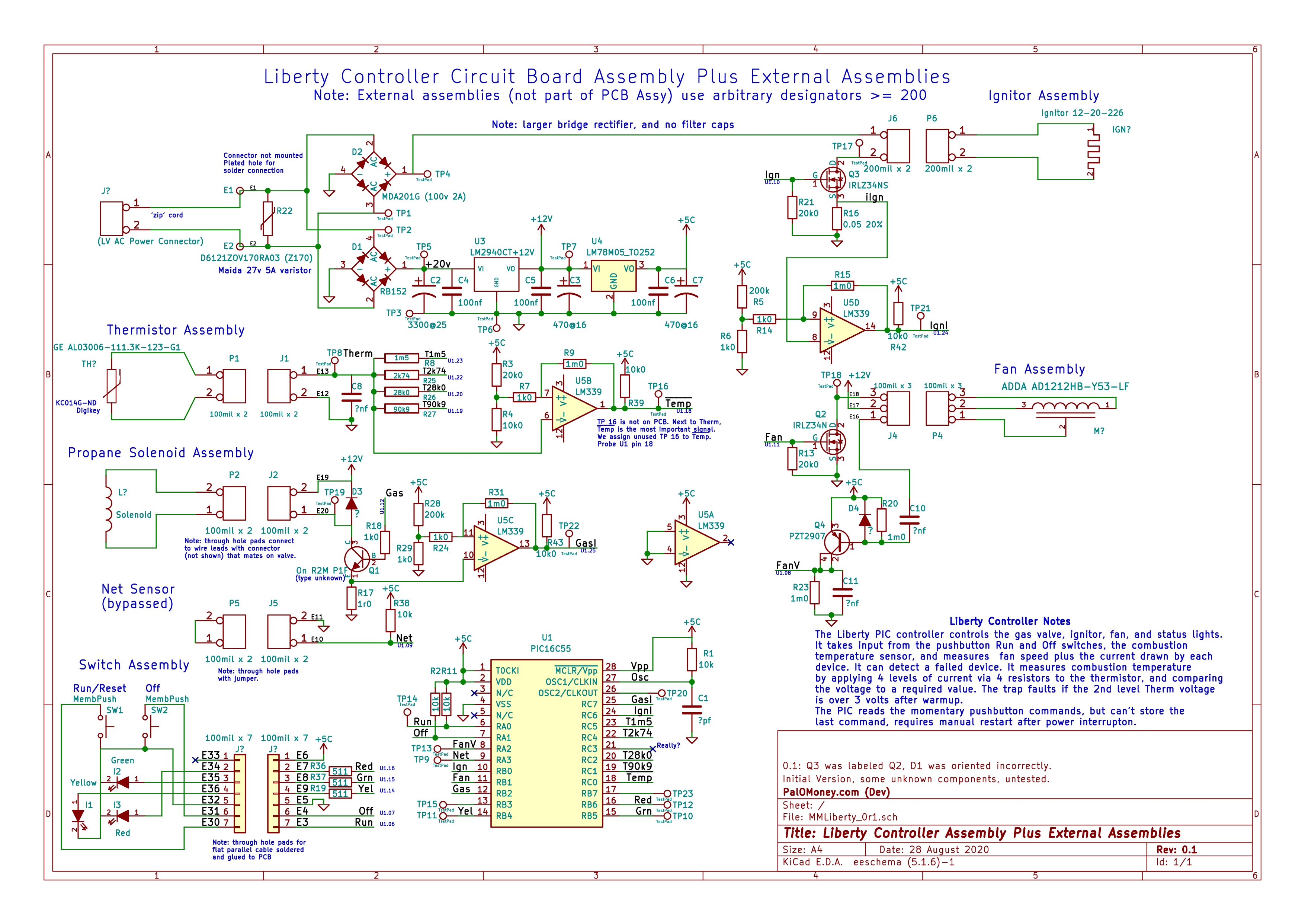
Sorry, only registered users may post in this forum.