Home
>
Mosquito Magnet
>
Topic
Independence Model version...
Posted by Independence
|
Independence Model version... July 06, 2020 06:15PM | Registered: 3 years ago Posts: 152 |
Just found this site and was glad to see other folks having a similar journey to my journey with the Independence model.
I'm not going to detail my whole project but just give an overview. If anyone wants more information, I will be happy to post more.
The Independence model is fundamentally the same, but is battery powered and has a Thermo Electric generator in it to power it when it is running. The battery is only used to bring it up to operating temperatures. I believe the same basic designed is used in the current Executive model and the discontinued Liberty Plus.
Similar to the other models, it has a host of issues that can prevent it from running, including corrosion of the main controller board. As part of my journey in getting a difficult unit to run, I actually had a new PCB made but once I had that, it turned out that one of the AD inputs of the PIC controller was shot, so I re-spun another board with an Atmega32U4 controller and wrote my own software. At that point, I had reversed engineered it enough that it wasn't difficult to write it and was much more flexible. Wifi was also added to it, so I am able to monitor and control it via the web.
Here are some things I learned about it that may be applicable to other models as well:
1) The Independence model has a shroud around the combustion chamber that takes positive pressure from the fan and injects it into the chamber. I found that the faster the fan runs, the faster the unit heats up to temperature. Normally, from when the igniter starts and the solenoid triggers, it can take about 20 mins to reach operating temperature. Their program runs the fan at half speed until the thermo electric generator generates enough voltage. I ran the fan at full speed once I detected ignition and that reduces the ramp time to less than 10 minutes.
2) The nozzle can easily be cleaned with MAF or Carb cleaner, including the bronze filter. In my case, the nozzle is a Delavan 1.75 45 degree A cone filter. They are not easy to find as most nozzles are for oil burners with wider angles, but I found that it is quite easy to disassemble and clean the insides to restore performance.
3) I had a unit that was not coming up to temperature and despite swapping nozzle and regulator with another good unit, it was still low. The only thing left to try was to clean the catalytic converter. You could clearly see through it so it wasn't clogged, but since I had nothing else to try, I sprayed MAF cleaner through the converter. Since it doesn't leave any residue, I figured I didn't have anything to loose. After the cleaning, the unit now comes up to temperature quickly and runs at the high end of the sweet spot.
4) The Independence doesn't seem to have the igniter problems that earlier models have. There is a separate igniter board that generates the high voltage and the controller board just provides a pulldown to activate it. My algorithm for detecting ignition is to leave the igniter on for 15 seconds after the solenoid is energized, while waiting to detect a 0.2v positive change in the thermistor voltage within a minute. I've not seen a case where it hasn't ignited yet.
5) Although the Independence is designed to work on a battery, I hooked up a power supply to one of them as I wanted to implement a reduced propane mode. Basically, a web scheduler would put the unit in fan mode at 7am in the morning, where the propane is turned off, but the fan is kept running at full speed to keep dehydrating the mosquitos. At 7pm, the scheduler would then initiate normal running mode. So that saves about 50% of the propane use.
6) For the battery powered unit, I let it run till about 1 or 2pm and then put it in hibernate mode, where it just goes to sleep. On hot days, most of the mosquitoes have died by then, but on cool or rainy days, they may not. There is enough battery to last till it resumes normal operation, where the batteries can get charged. I'm thinking the propane saved is enough to just give up battery power and run a power supply to it...
I guess that's enough for a first post. If anyone is interested or needs help with their unit, I would be happy to provide more information..
|
Re: Independence Model version... July 08, 2020 02:59PM | Admin Registered: 7 years ago Posts: 164 |
Interesting post. I didn't dare try the Independence because of reported reliability issues, even though it would be great to run a trap away from ac power.
I don't know how many Independence users are DIY types, but those that are could certainly use whatever information you care to share. I don't know how many questions or responses you will get here, as this is a low-volume hobby site that has highlighted the Defender and Liberty.
Your detailed experiences trying to repair then re-engineer and now maintain your traps would make good reading, with ongoing updates as appropriate (e.g, see the blog which details the ongoing struggle).
Notes, drawings, and photos of the stock unit would be most helpful for those trying to fix their trap. The new project design topic would be terrific. These can be posted here on the forum, and/or added to the wiki with links to the wiki here.
It sounds like you have solved most of the problems with the Independence! The MAF (Mass Air Flow Sensor) cleaner trick on the catalyst is new to me. I'll get some and try it. Because I instrument and record the combustion and ambient temperatures and humidity, I have a record that I can compare between the original year 2002 catalyst and a cleaned one, and some questions as to their so-far unexplained variability. Thanks a lot for the tip.
I am envious of your 7AM to 7PM idle time. I wish that I didn't have to worry about mosquitos during that extended period. I suffer from mosquitos after 4 PM and before 9 or 10 AM.
Good luck with the mosquito season!
|
Re: Independence Model version... July 09, 2020 02:51PM | Registered: 3 years ago Posts: 152 |
Well, I actually found your site while googling for information, so I thought it would be useful adding some Independence info here. You never know who is searching for information out there. Your blog and Wiki makes good reading for folks like us who just cannot understand why something that has such a simple premise has so many problems. There appears to be a lot more Defenders and Libertys out there than Independence. I didn't pick it per se, it was just what I found for free on Craigslist. At this point in the game, I can account for pretty much every issue on the Independence and having control of the controller board and firmware allows me full flexibility. I will post the schematics and some pics here to start off and if there are interested parties, they can chip in.
|
Re: Independence Model version... July 09, 2020 03:52PM | Registered: 3 years ago Posts: 152 |
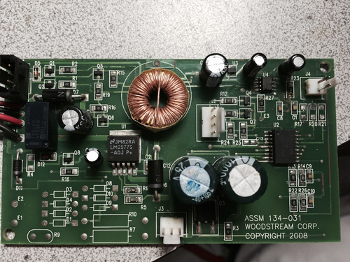
Ok, I'll start off with the main controller board. Due to a lack of, or insufficient conformal coating, the boards were partial to corrosion. Attach below is a picture of an original board.
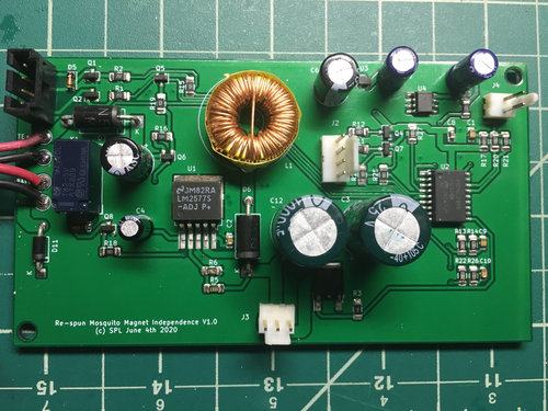
You can clearly see corroded tracks and pads. Since I had two units and one was working and the other wasn't, I decided it would be worthwhile to re-spin the board. I already had the schematic traced out so it wasn't too much work to lay out a PCB. This is the result. I just transferred all the parts from the non-working board to the new board.
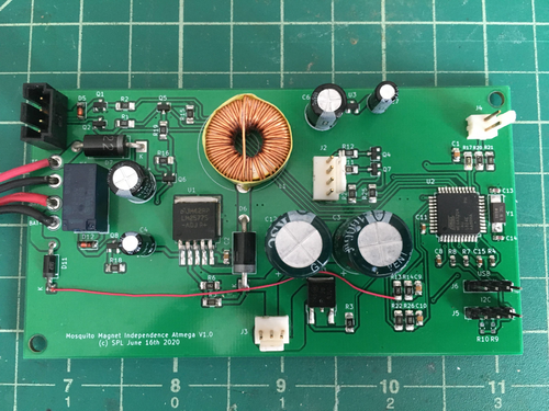
I thought this would solve the problem where the non-working unit would just reach working temperature and then just shut down with a no gas error. However, the re-spun board exhibited the same error and it turned out that the AD input for the Thermo Electric generator to the PIC chip was shot. Apparently, once it reached operating temperature, it starts checking to see if there is generated power, and if there isn't (due to bad AD input), it assumes an error, and shuts down. Since there was no way to get a replacement PIC, I decided to re-spin the board with my own controller and just re-write the firmware myself. At this point, I had been test running the unit on my bench with a variable resistor as the thermistor, so I was aware of all the temperature points and what the unit did at each point. I choose the Atmega32u4 chip since that was what I used in all my other projects. The resulting controller board is shown below:
The red rework wire didn't turn out to be necessary. The schematics for both boards will be in the next post since I can only post 3 pics in each post. The new board has a USB interface so I can update the firmware from the outside without dismantling the unit. It also has a serial i2c interface to a Wemos/NodeMCU Wifi module board for wireless connectivity. That module only handles the wifi, web interface and MQTT interface for the main controller, and isn't required for normal operation.
|
Re: Independence Model version... July 09, 2020 04:15PM | Registered: 3 years ago Posts: 152 |
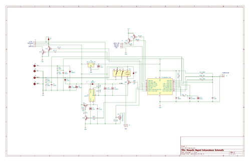
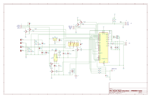
The original schematic for the Independence board is attached below:
And the re-spun Atmega32u4 version is below:
I didn't re-design any of their circuitry, just replaced their PIC controller with the Atmega32u4 chip. They had a reference chip in their design, and I didn't quite understand the reason for it, so I removed it from my version. Also, the 5V LDO regulator they used couldn't quite supply the current for the Atmega chip, so that had to be replaced with a version that could supply more current. Since I took all the components from the original board, I didn't identify all the components. The transistors are standard NPN and PNP transistors of the 2N2222 and 2N2907 family.
The controller basically has digital controls for the gas solenoid, igniter, two LEDs, charging relay, and the Fan voltage controller, and AD inputs for the Battery voltage, the Thermo Electric generator voltage, and the Thermistor voltage. The thermistor input is a 2 stage circuit to cover the wide range of resistance of the thermistor, basically from over 200 KOhms to about 500 Ohms, which the unit considers the threshold of over temperature. The thermistor is a 200K@25C B25/85=4623 device. I could never find an exact spec device but the closest is a Digikey part # KC014G-ND, which is a 200K@25C B25/85=4365 device.
For what it's worth, since I didn't end up using any of the re-spun original boards, I have 5 PCBs available for just postage to anyone who needs a clean board to replace their corroded board.
Edited 1 time(s). Last edit at 07/09/2020 04:38PM by Independence.
|
Re: Independence Model version... July 09, 2020 05:03PM | Registered: 3 years ago Posts: 152 |
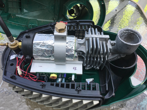
Here are some pictures of the unit itself:
From left to right, there is the nozzle, combustion chamber, catalytic converter, and plume chamber. There is a large finned heatsink under the catalytic converter, which sits right under the fan. The fan draws air from the top chamber down past the finned heatsink and out through the sides of the unit. Between the heatsink and the catalytic converter is the Thermo Electric generator, which is just aPeltier Seebeck device.
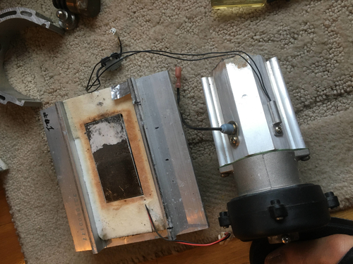
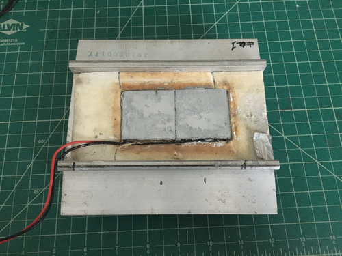
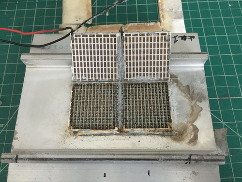
In the dismantled picture above, you can see the device in the middle of the heatsink. This particular one was shot and not working anymore, but I've located some replacement units and will be trying them out soon. The temperature difference is enough to power the fan and electronics, and even charge the batteries a teeny bit. On the catalytic converter, you can see the igniter and thermistor.
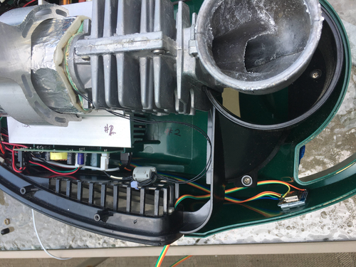
Here, you can see how the electronics sit in the unit. The main board slots in on the left in it's original position. A four wire i2c interface runs to the wifi board on the right, which is just double sided taped to the inside of the handle. The wifi module also has the ambient temperature sensor, which is just a Dallas Semi 18B20 device which hangs loosely outside the unit.
Edited 1 time(s). Last edit at 07/14/2020 08:50PM by Independence.
From left to right, there is the nozzle, combustion chamber, catalytic converter, and plume chamber. There is a large finned heatsink under the catalytic converter, which sits right under the fan. The fan draws air from the top chamber down past the finned heatsink and out through the sides of the unit. Between the heatsink and the catalytic converter is the Thermo Electric generator, which is just a
In the dismantled picture above, you can see the device in the middle of the heatsink. This particular one was shot and not working anymore, but I've located some replacement units and will be trying them out soon. The temperature difference is enough to power the fan and electronics, and even charge the batteries a teeny bit. On the catalytic converter, you can see the igniter and thermistor.
Here, you can see how the electronics sit in the unit. The main board slots in on the left in it's original position. A four wire i2c interface runs to the wifi board on the right, which is just double sided taped to the inside of the handle. The wifi module also has the ambient temperature sensor, which is just a Dallas Semi 18B20 device which hangs loosely outside the unit.
Edited 1 time(s). Last edit at 07/14/2020 08:50PM by Independence.
|
Re: Independence Model version... July 09, 2020 05:26PM | Registered: 3 years ago Posts: 152 |
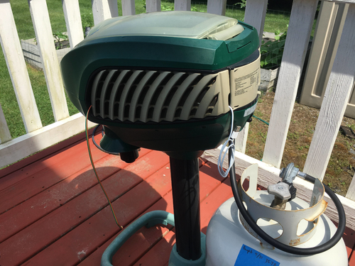
So that's how it looks from the outside. The white cable is the USB cable to the Atmega and is used to monitor as well as update the firmware. The cable dangling out the front is the ambient temperature sensor.
Here's how the web interface looks like:
It's a rudimentary interface that just contains the minimum. Fan mode shuts off the gas and just runs the fan at full speed. It's what I use during the day to continue to dehydrate the mosquitoes. Hibernate is used to shut down the unit but still allow it to respond to a Normal command. This is used in the Battery version. The Options A, B, C, D and Flag 1 and 2 are placeholders in the web server to pass parameters to the Atmega controller without re-programming the Wifi module. You'll notice I didn't run the USB from the Wifi module out so I have to dismantle the unit in order to re-program it. So those placeholders let me add options to the unit by just programming it on the Atmega side.
MQTT telemetry is also supported and can be enabled or disabled via the web screen. Everything on the screen is logged. Scheduling is handled externally, so no clock is required in the unit. You could use any web scheduler but I use Open Sprinkler software to do it. I already have it running for my lawn sprinklers and it allows you to define any new virtual zones via URLs, so the Mosquito Magnet is just another zone that happens to run for 12 hours at a time! Zone ON sets Normal mode, while Zone OFF sets Fan mode.
Ok, I think that about sums it up. I didn't post any code , though I'm happy to share privately with anyone who wants to implement the same thing. I just don't like posting code for critique on the Internet... :)
|
Re: Independence Model version... July 14, 2020 02:24AM | Admin Registered: 7 years ago Posts: 164 |
Great post. I looked over the original circuit diagram, and was impressed by how simple it was. Your post was very informative. I feel I could fix an Independence with this information. But because more is better, it would be even better for you to write and post a detailed circuit description. You could use the wiki for that. I don't have enough information (e.g., battery and TEG, voltages, waveforms, etc.) to do it myself.
Is Q2 a bipolar transistor used to switch the igniter with only 2ma of base drive? Perhaps it is a MOSFET like the fan driver. The transistor drivers for the LEDs are remarkable. You would think that the PIC could drive high-efficiency LEDs directly.
Since that PIC seems to have 4 analog inputs, are they still using the stepped waveform to determine temperature, or is there an analog measurement happening? The NodeMCU Defender Add-On, which has an ADC input, just uses a simple voltage divider, and it is quite sufficient to detect a wide range of temperatures. I wonder about the various scales (R17, R21, R20). And what's with R23, U4, and C11, some sort of timing circuit?
So the Peltier TEG charges the battery directly through D7 and the relay? No charge controller circuitry. And the boost converter U1 is enabled by a PIC output, presumably to not discharge the battery when not running. Is there an external bootstrap power supply connection?
|
Re: Independence Model version... July 14, 2020 09:53PM | Registered: 3 years ago Posts: 152 |
dev Wrote:
-------------------------------------------------------
> e is better, it would be even better for you to wr
> ite and post a detailed circuit description. You c
> ould use the wiki for that. I don't have enough in
> formation (e.g., battery and TEG, voltages, wavefo
> rms, etc.) to do it myself.
Umm, that would actually be like work :), especially since most of the investigation took place over 2 years ago. Only the new controller and firmware was recent. Maybe when I'm retired, but for now I'd rather just respond to questions as they come up...
>
> Is Q2 a bipolar transistor used to switch the igni
> ter with only 2ma of base drive? Perhaps it is a M
> OSFET like the fan driver. The transistor drivers
> for the LEDs are remarkable. You would think that
> the PIC could drive high-efficiency LEDs directly.
>
Yes, Q2 is just a regular bipolar transistor. What I didn't show or even dig into is the secondary board in the unit, which handles the igniter and solenoid. There is some high voltage generator on that board that appears to be driven by the pull down. None of those boards ever failed for me, so I never delved into them.
As for the LEDs, I think they were an ancient design, not bright at all. I never measured how many ma they consumed. The PIC was a low power version, so maybe it didn't have the drive. The atmega certainly could have driven them but I decided to leave the first design as identical as possible.
> Since that PIC seems to have 4 analog inputs, are
> they still using the stepped waveform to determine
> temperature, or is there an analog measurement hap
> pening?
No, the PIC was reading the temperature directly via an analog measurement of the thermistor voltage divider. Due to the large operating range of the thermistor (more than 200k down to about 400 Ohms), they used two digital outputs of the controller to change the ratio of the voltage divider. At about 80 degrees, the thermistor voltage is about 3.3v in the high range, which is R21 driven high, and R20 set to input mode. When the unit is heating up, this voltage will drop to about 1v, at which point the PIC sets R21 to input and drives R20. This switches to the low range, re-starting at about 3V, and this keeps dropping until it reaches 1.35v, which is when the LED turns green and it is in operating mode. When this voltage reaches 0.2V (about 450 Ohms), the unit shuts down, presumably from an over temperature condition. The lowest voltage I've seen in a just cleaned catalytic converter is about 0.43v. If the voltage rises to 1.7v or so, it also shuts down, as a detection of lack of combustion or running out of gas.
The NodeMCU Defender Add-On, which has an
> ADC input, just uses a simple voltage divider, and
> it is quite sufficient to detect a wide range of t
> emperatures. I wonder about the various scales (R1
> 7, R21, R20).
As mentioned above, R17, R21 and R20 just forms a variable range voltage divider with the thermistor. R17 is at 5V and connects to the thermistor to ground.
> And what's with R23, U4, and C11, so
> me sort of timing circuit?
It's a voltage reference circuit at 2.5v. I'm not sure why they had it. Maybe the PIC didn't have an analog reference and they needed the external reference. In any event, the Atmega didn't need it so I took it out.
>
> So the Peltier TEG charges the battery directly th
> rough D7 and the relay? No charge controller circu
> itry.
I know I said Peltier, but I've since been informed that a generator is a Seebeck device. The Independence model actually uses non-rechargeable cells, so it never actually charges. I believe that circuit is there from the Liberty Plus, which uses rechargeable batteries. With those diodes and the relay, this is how I believe it works for charging vs non-charging:
When the relay is OFF, D11 is actually shorted by the relay, which allows any positive forward voltage from the TEG to charge the batteries.
When the relay is ON, D11 prevents any voltage from flowing back into the batteries. This is the mode for the Independence.
So for my own battery version firmware, I leave the relay off, allowing charging until I detect the battery voltage rising above 6.09v. At that point, I turn on the relay, disabling charging. In practice, the TEG can maintain the batteries, but cannot really charge it from a low level. So, my thought of running the fan on batteries for a few hours a day doesn't really work. A fully charge set CAN run it for 2 hours and then hibernate (everything off) for a few hours, and still restart, but it cannot charge enough overnight to repeat this. So, if I want to run propane saving fan mode, I'm going to have to run wired power out to the unit.
> And the boost converter U1 is enabled by a P
> IC output, presumably to not discharge the battery
> when not running.
Yes, the power switch is actually just an input to the PIC, so it is never really off. So, when the switch is off, the PIC turns everything off and put itself into sleep mode. I implemented the same thing for the atmega version, but since I wanted to keep wifi running, it was really moot.
Is there an external bootstrap p
> ower supply connection?
Not on the Independence. I just put power in via the battery connector.
|
Re: Independence Model version... July 15, 2020 09:47PM | Registered: 3 years ago Posts: 152 |
> What I didn't show or even dig into is the secondary board in the unit, which handles the igniter and solenoid.
> There is some high voltage generator on that board that appears to be driven by the pull down.
> None of those boards ever failed for me, so I never delved into them.
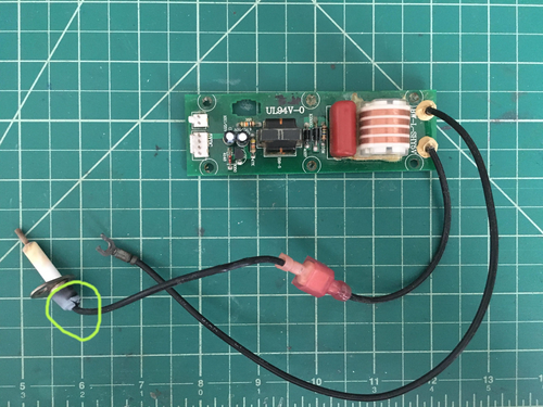
Ha ha, Murphy must be around! Today, the unit wouldn't ignite and I had to dig in a bit. The igniter was firing as I could hear it clicking away, but the gas wouldn't ignite. Since I had to disassemble and investigate, here is a picture of the secondary board:
The 4 pin connector comes from the controller board and the 2 pin connector goes to the solenoid. The solenoid drive comes from the 4 pin connector and goes right out the 2 pin. The igniter pull-down from the controller goes to another transistor and then to a couple of transformers and a large capacitor. I think it's some kind of charge/discharge circuitry, ala photo flash.
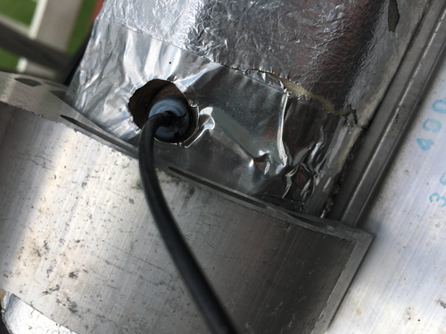
Anyway, you can see where the problem ended up being (circled). The igniter's insulation boot was cracked, and the next picture shows where it was arcing to:
It was actually arcing from the inside of the boot to the metal tape on the fiberglass insulation of the catalytic converter. This arcing was preventing the arc INSIDE the converter, thus resulting in no ignition. From the outside, everything seemed fine, it was happily clicking away, but no flame! I can't call this a design problem since it was probably caused by my numerous dis-assembly/assembly activities.
Just another day in Mosquito Magnet land..... :)
|
Re: Independence Model version... July 16, 2020 11:29AM | Registered: 3 years ago Posts: 10 |
|
Re: Independence Model version... July 27, 2020 08:43PM | Registered: 3 years ago Posts: 7 |
Dear All,
I own a liberty plus MM which is very similar to the independence(at lest according to the drawing)
I had an issue with my Thermo Electric generator. Even without switch on the system, one could hear that the igniter continuously working. Switching on the system it continuously try to blow the gas inside which makes big flames coming out from the turret (absolutely scary and dangerous in my opinion)
Finally I found out that is because of TEG. In system there are a 40x80mm size. This is not a common one, there is no number on it.
In commercially 2 main types are both 40x40
1. SP1848-27145 4,8V DC
2. 12710 12V DC; on ebay this sold as MM spare part.
Which one do we need? In the first case I need to connect two series? or in the second case two in parallel (or only one piece needs).
Thank you very much for your help
|
TEG and Malfunctioning Independence July 28, 2020 02:09AM | Admin Registered: 7 years ago Posts: 164 |
I don't know about TEG modules, but this sounds like a controller problem.
The TEG also may be bad, but there is a problem that keeps the igniter on and the gas flowing, even when switched off. If you disconnect the TEG and just attach a battery or power supply, does the unit work?
You should fix these issues first, then figure out the TEG. Look at one of the earlier posts in this topic for a partial schematic of an Independence. Can you troubleshoot from the schematic?
Good luck!
|
Re: TEG and Malfunctioning Independence July 28, 2020 02:40AM | Registered: 3 years ago Posts: 152 |
I agree with dev, I don't think your problems have anything to do with the TEGs. They basically supply power to the unit when the unit is running. Your controller appears to be out of whack. The fact that it is turning on the igniter when the switch is off is a sure sign something is off. Also, the gas regulator is very low pressure, 11 WC, and the flame coming out of the nozzle barely makes it past the combustion chamber, much less through the catalytic converter. Your gas regulator may be faulty. When you turn it on, does it go through the initial high speed fan purge, followed by about a minute before the igniter comes on? A few seconds after the igniter starts firing, the gas valve is activated. If your's is not doing this, then something is wrong with the controller.
On the topic of the TEGs, I have tried the eBay 40x40mm TEGs, and while they are the right size and voltage, they don't appear to provide enough current at the working voltage. I used two in series.
On the topic of the TEGs, I have tried the eBay 40x40mm TEGs, and while they are the right size and voltage, they don't appear to provide enough current at the working voltage. I used two in series.
|
Re: Independence Model version... July 28, 2020 06:58AM | Registered: 3 years ago Posts: 7 |
Thank you for your absolutely fast response!!
I have just disconnected the TEG and really strange but the error is gone. The system could switch on without any error, got the solid green. I left during overnight and probably my battery is discharged. Maybe I have some errors in the charging circuit and if TEG is not connected it can not couse error.
Today I am going to connect to a 5V power supply.
I guess you tried the first type of TAG.
|
Re: Independence Model version... July 28, 2020 10:17PM | Registered: 3 years ago Posts: 152 |
With a fully charged battery, the MM can probably run for 4-5 hours. I think the Liberty Plus battery is about 3000 maH and the fan and electronics draw about 700-800ma, so do the math. The TEG is essentially in parallel with the battery, with diode isolation, so I am surprised that it made the difference. Did you try plugging the TEG back AFTER the unit turned green? I don't know if you have any test equipment, but measuring the voltage of the TEG and battery when both are connected is probably the first step.
Yes, I tried the SP1848-27145 TEGs and as mentioned in the other thread, they didn't have as much power as the OEM TEGs. I still have to do some measurements...
Yes, I tried the SP1848-27145 TEGs and as mentioned in the other thread, they didn't have as much power as the OEM TEGs. I still have to do some measurements...
|
Re: Independence Model version... July 29, 2020 01:30PM | Registered: 3 years ago Posts: 7 |
I connected the system to 5V yesterday. It works as it should without the TAG. It goes to solid green looks everything fine (the fan speeds up, but after around 5 minutes the system switch off and I got the error (green and after it very shortly red- according to docu it is high themperture reading. Maybe I put something wrongly together.I have all necessery tools even scope as well just in case.
|
Re: Independence Model version... July 29, 2020 02:21PM | Registered: 3 years ago Posts: 152 |
From what I gathered with the Independence (and I presume also with the Liberty Plus), what happens is that after reaching operating temperature, the controller starts to check the voltage of the TEG. If it doesn't detect acceptable voltage, it shuts down with an error code of insufficient gas. It appears to interpret the lack of or insufficient TE voltage after reaching operating temperature as lack of combustion, attributed to running out of gas.
If your error is really over temperature, then you should really check your gas regulator. I'm not sure if it can reach operating temperature (about 130C), and then proceed to over-temperature (probably over 215C) in just 5 mins unless your combustion is very over-active
If your error is really over temperature, then you should really check your gas regulator. I'm not sure if it can reach operating temperature (about 130C), and then proceed to over-temperature (probably over 215C) in just 5 mins unless your combustion is very over-active
|
Re: Independence Model version... July 29, 2020 07:11PM | Registered: 3 years ago Posts: 7 |
I have learned a lot from all of you. Thanks.
Today I could go further. I find out that I reached the solid green and after an over temperature rapidly as I have removed the TEG, but did not take care of the gap, and there was no right connection between heat sink and cathalytic converter.
Now I used some heat pasta and made a very good connecton. It looks too good. It takes much longer to reach the high speed fan stage (should 6-7 minutes), but after that I can not get solid green. After a longer period I got gas out error. Probably much much slower but I reached the right temperature and than as you mentioned it checked the TEG and as I have removed it just switched off.
As I thought that everything ok with just remove the TEG, I throw it away. :-(So I need to buy a good size and type one...
|
Re: Independence Model version... July 29, 2020 09:28PM | Registered: 3 years ago Posts: 152 |
Well, if you want to run it in power supply mode, all you have to do is connect the power supply to both the Battery and the TEG input connections on the main board. Then the unit should run ok.
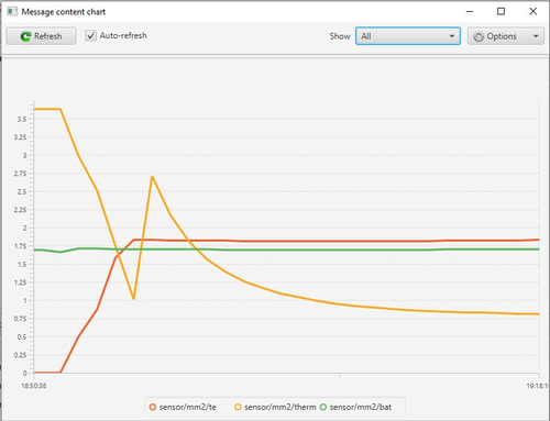
Normally, it can take anywhere between 15-25 mins to reach operating temperature. On the Independence and Liberty Plus, the fan transitioning to high speed is a sign that the system thinks the TEGs are up to voltage. As a reference, here is a plot of the Bat, TEG and thermistor voltage on a working Independence, utilizing my own software:
You can see the TEG voltage (multiply by 3x to get real voltage) rises above the battery voltage shortly before the thermistor voltage divider changes range. At the point when the TEG voltage maxes out, it is starting to carry the whole load and it can run without the battery.
|
Is the TEG a critical thermal impedance? July 31, 2020 03:58PM | Admin Registered: 7 years ago Posts: 164 |
As I thought that everything ok with just remove the TEG, I throw it away.
So bolting the heatsink to the combustion chamber results in a too-low internal temperature? Does this mean the TEG is a critical thermal impedance? I remember that the original Defender software requires the cover in place to reach operating temperature, that fooled me several times. Did you try putting on the cover? If that still doesn't work, try inserting a thin thermal insulator between the heat sink and the heat source to see if that makes a difference.
You can see the TEG voltage (multiply by 3x to get real voltage)
That is a very informative plot. So the TEG is generating 3 x 1.85 or 5.55 volts, and the battery indicating 5.1 volts. What is the battery? Do you know how much current the TEG is supplying?
|
Re: Is the TEG a critical thermal impedance? July 31, 2020 06:04PM | Registered: 3 years ago Posts: 152 |
That is a very informative plot. So the TEG is generating 3 x 1.85 or 5.55 volts, and the battery indicating 5.1 volts. What is the battery? Do you know how much current the TEG is supplying?
In this plot, I am using 4 x 1.2V Nimh batteries, so 4.8V nominal. When set in charging mode, the OEM TEGs can drive the fan at full speed (~800 ma), drive my controller and wifi board (~110ma) AND provide maybe 80-100ma for charging. So, I would guess the TEGs are capable of supplying about 2.75W each, for a total of 5.5W.
I'm still playing with the eBay TEGs and in the process I'm finding out that the OEM controller board was a finely tuned machined. The batteries for the Independence is 4 alkaline cells, while the Liberty Plus is 4 nimh cells. So the voltage at the Bat terminals could be as low as 4.8V nominal. Well, guess what, there is a 5V LDO regulator on the board and the PIC is a 5V device. So during startup, the PIC could be running at less than 5V, hence the need for the 2.5V reference for their ADC. It is only after the TEGs start to generate more than 5V that the voltage stabilizes. With my Atmega32U4 controller, the ADC was more susceptible to inaccuracies when VCC was less than 4V, which can happen when I run the fan at full speed before the TEGs come up to voltage. So they had sized the TEGs and managed the power consumption quite tightly in order to make it run at the low end of the battery voltage.
BTW, did I upload too many pictures to this thread? Your database seems to be crashing trying to load the pictures in this thread.
|
Re: Is the TEG a critical thermal impedance? August 01, 2020 06:47AM | Registered: 3 years ago Posts: 7 |
My answer is YES!
-If you connect the heatsink to combustion chamber the system not able to reach the necessery heat. No solid green
-If you just let it loose (no real connection between the two) than in a couple of minutes you get an overheat (green/red)
I finally could make my system up and running (2 days now) with cord the 5V to the system. I find the old wrong TAGs in the rubbish (discusting job) and placed back but not cennected). THe controller does not check the TEG voltage. Even without the connection the system is running.
I am waiting the TEGs from ebay(I ordered 2 from both types) and will play with them. Paralel, serial , 2 or 1, etc....
BTW, the images come up very slowly or not at all.
One more question, you are mentioned your own controller. Do you have some more technical detail from it? I mean board drawing, PIC program, part list etc etc. I do not know that you want to share it, as it is your work. I just wondering that it would be good to reduse the gas usage by half. I do not use pure propan(that would be 2-3 times more expansive) but propan/butan which is 11.5kg and used in household applications.
Thanks all
|
Pictures Slow No More? August 01, 2020 04:12PM | Admin Registered: 7 years ago Posts: 164 |
BTW, did I upload too many pictures to this thread? Your database seems to be crashing trying to load the pictures in this thread.
BTW, the images come up very slowly or not at all.
So they were/are. Made several adjustments to the site, now it seems better (i.e., instant loading), not perfect, but time will tell... Evidently an error in the picture handling module caused the system to be too slow, and just give up after a certain amount of time.
We don't want to worry about pictures. There can almost never be too many pictures (famous last words). I know I would like to see more.
Edited 1 time(s). Last edit at 08/01/2020 05:41PM by dev.
|
Controller Detail August 01, 2020 05:48PM | Admin Registered: 7 years ago Posts: 164 |
One more question, you are mentioned your own controller. Do you have some more technical detail from it? I mean board drawing, PIC program, part list etc etc. I do not know that you want to share it, as it is your work. I just wondering that it would be good to reduce the gas usage by half. I do not use pure propane (that would be 2-3 times more expansive) but propane/butane which is 11.5kg and used in household applications.
There is a lot of detail available. Start with the Defender NodeMCU Design forum topic. It has links to the related wiki and blog. The details are on the wiki, recent project history on the blog. Use that topic to ask questions.
There is a new design in the works. I might have to adapt it for use in my Independence, and now, sadly, my Patriot, which, sadly, stopped working yesterday. Perhaps you could adapt it to operate only during certain hours or conditions.
|
Re: Controller Detail August 01, 2020 06:09PM | Registered: 3 years ago Posts: 152 |
Maybe you missed it earlier in this thread because of the slow picture loading, but the schematic of the Independence, as well as my replacement controller and board has already been posted. With the exception of the micro controller, it uses all the same components on the Independence or Liberty Plus board.
|
Re: Is the TEG a critical thermal impedance? August 01, 2020 06:22PM | Registered: 3 years ago Posts: 152 |
> -If you connect the heatsink to combustion chamber the system not able to reach the necessery heat.
> No solid green -If you just let it loose (no real connection between the two) than in a couple of minutes you get
> an overheat (green/red)
I'm not sure I understand. You say that you have it running for 2 days now, but based on your statements above, it either doesn't go green, or it overheats. BTW, 5V may be too low a power supply voltage for the unit if your TEGs are not working. On the Independence, the TEGs generate over 6V in operating mode.
> use pure propan(that would be 2-3 times more expansive) but propan/butan which is 11.5kg and used in
> household applications.
I wonder if this changes the catalytic reaction in the converter. I believe the premise is that carbon dioxide is produced from the propane catalytic combustion. Since you have less proportion of propane, maybe less CO2? I don't know if the makeup of Butane will result in CO2 production on combustion...
|
Some feedback on eBay TEGs.. August 03, 2020 10:37PM | Registered: 3 years ago Posts: 152 |
Well, file this under "You get what you pay for..", and "RTFM"....
As mentioned earlier, I had replaced the faulty TEGs in one of my Independence with these SP1848-27145 TEGs from eBay. My initial impressions was that they didn't produce as much, or enough power to operate the Independence. Today, I decided to measure exactly how much power they produced. Before I did that, I thought I should check to make sure I had enough thermal grease on the units. Here's what I found:
These are the replacement TEGs, connected in series, in place of the original TEGs. I did have enough thermal grease on them.... BUT.. here's what I found after a few nights of running this unit....
The units had pretty much disintegrated from the high temperatures. The leads had come off, and the devices had come apart... In checking the specifications (the RTFM part...), they are only rated for 150C, and the Independence catalytic converter runs at about 200C, especially during the hot day. Before they fell apart, they WERE generating power though, but now that are essentially destroyed, I didn't have a way to measure them anymore. HOWEVER, I did have one spare, and decided to sacrifice it to do some measurements. So, I placed my last single unit back in place and fired it up. Here's what I measured:
At operating temperature (Thermistor indicating temperature of 195C) with no load, it was indicating 6.33V. When I loaded it with a 12V bulb, the voltage dropped to 3.4V, at a current draw of 650ma. So the single TEG is only producing about 2.2W and I believe the OEM TEGs produce about 2.75-3W each. So, when you take into account the lower power and lower temperature, the SP1848-27145 TEGs are really no substitute for the OEM TEGs.
Now, I had also recently purchased a couple of the TEC1-12710 TEGs as well to try out. Those are supposed to be Peltier cooling devices, but I thought I'd try them out as TEGs. I haven't received them yet, but from the pictures, I now don't have high hopes for them. Even the TEGs on ebay that are sold as replacement for Mosquito Magnets are still rated at 150C, so they are not really for the Independence or Liberty Plus.
Until someone comes up with a source of better (and affordable) replacement TEGs for the Independence and Liberty Plus, it looks like they will be operating in tethered mode....
|
Re: Some feedback on eBay TEGs.. August 04, 2020 12:04AM | Admin Registered: 7 years ago Posts: 164 |
At operating temperature (Thermistor indicating temperature of 195C)
Wow! I wonder, why so hot? The Defender exhaust just after the catalytic converter runs at about 80-95°C above ambient. Mine is set to trigger an over temperature fault at 140°C, which has never happened. It uses 20 lbs of propane every 21 days. Isn't this about the same as the Independence? The Defender heatsink, cooled by the suction and combustion fan, comes after the thermistor. (I haven't measured the combustion chamber temperature at the hottest point, perhaps it is also as hot.)
I remember the patents talking about exhaust temperatures of about 115°F. Is your exhaust temperature running hot as well? If so, it sounds like the thermal impedance is too high, which could be a problem with heat sink cooling or thermal conduction. What is the heat sink temperature? Does the fan always force cool the heatsink? Is the case temperature close to the thermistor temperature?
When shopping, have you found a device rated for over 200°C? Is there a way to determine the OEM and part number? I doubt the Mosquito Magnets have high enough volume to warrant an expensive, custom high spec part. Au contraire. Keep looking, perhaps you will find it. Quite the mystery.
BTW, still working on the picture loading issue.
Defender:
Temp=112.5C (0) at 5:35224 F=1 I=0 G=1 S=1 E=0 T=34.2C H=37.6% M=8664 (286/1011:7426) R=70~140 W=-77 B=1.0 V=3.4
|
Re: Some feedback on eBay TEGs.. August 04, 2020 12:41AM | Registered: 3 years ago Posts: 152 |
> Wow! I wonder, why so hot?
Well, the thermistor on the Independence is placed right on the side of catalytic converter, so I presume it is the hottest point. The converter then sits on top of the TEGs, so I presume the temperature they are seeing is similar to what the thermistor is indicating. The other side of the TEGs are on the large finned heatsink, which is continually cooled by the main suction fan. I've never bothered to measure the temperature anywhere else, though I've felt the exhaust temperature at the bottom of the funnel and it seems like a normal warm human breath temperature. I could measure it I guess, just to get a data point.
> I remember the patents talking about exhaust temperatures of about 115°F. Is your exhaust temperature running hot as well?
I will measure this tonight.
> If so, it sounds like the thermal impedance is too high, which could be a problem with heat sink cooling or thermal conduction.
I don't believe so, as both my units behave the same. Yes, if the catalytic converter doesn't have good thermal contact with the TEGs and the TEGs to heatsink, the converter WILL run hotter, as evidenced by inarcs, but I believe mine are correctly seated.
> What is the heat sink temperature?
Never measured it. You can feel some warm air coming out of the side of the unit after passing through the heat sink, but it's not super hot.
> Is the case temperature close to the thermistor temperature?
Which case temperature? Nothing is going to be as hot as the thermistor right on the side of the cat chamber.
> When shopping, have you found a device rated for [ i]over[/i] 200°C?
I'll check Digikey for the specs of their TEGs...
> Is there a way to determine the OEM and part number?
I didn't find any markings on the units but they clearly work up to 200C as that's what my working unit has been doing for years.
Does the Defender only measure air temperature? That could explain why a single ADC range is sufficient to measure it. The Independence only measures the case temperature of the catalytic converter. As mentioned before, the thermistor temperature on the Independence goes from 20C to about 220C, which is when it go to an overheat condition.
Sorry, only registered users may post in this forum.
